Robotic tool changer

a tool changer and robot technology, applied in the direction of manufacturing tools, couplings, instruments, etc., can solve the problem of the piston moving accidentally past the failsafe position

Active Publication Date: 2011-08-23
ATI INDAL AUTOMATION
View PDF20 Cites 47 Cited by
  • Summary
  • Abstract
  • Description
  • Claims
  • Application Information

AI Technical Summary

Benefits of technology

[0005]In addition, the present invention entails a robotic tool changer having a first unit, a second unit, and a plurality of rolling members disposed in one of the units. A piston is movably mounted in one of the units of the robotic tool changer and movable between locked and unlocked positions. The piston includes a stem movable back and forth through an opening in the robotic tool changer. The stem of the piston and the opening are configured so as to at least slightly restrain the movement of the piston during at least a portion of the piston's movement as the piston moves from the locked position to the unlocked position. This restraint is intended to prevent the piston from inadvertently or accidentally assuming the unlocked position.

Problems solved by technology

In some situations it may be possible for the piston to accidentally move past the failsafe position.
For example, it is conceivable that because of vibrations or shocks or other external forces that the piston can accidentally move past the failsafe position to the unlocked position.

Method used


Image

  • Robotic tool changer
  • Robotic tool changer
  • Robotic tool changer

Examples


second embodiment

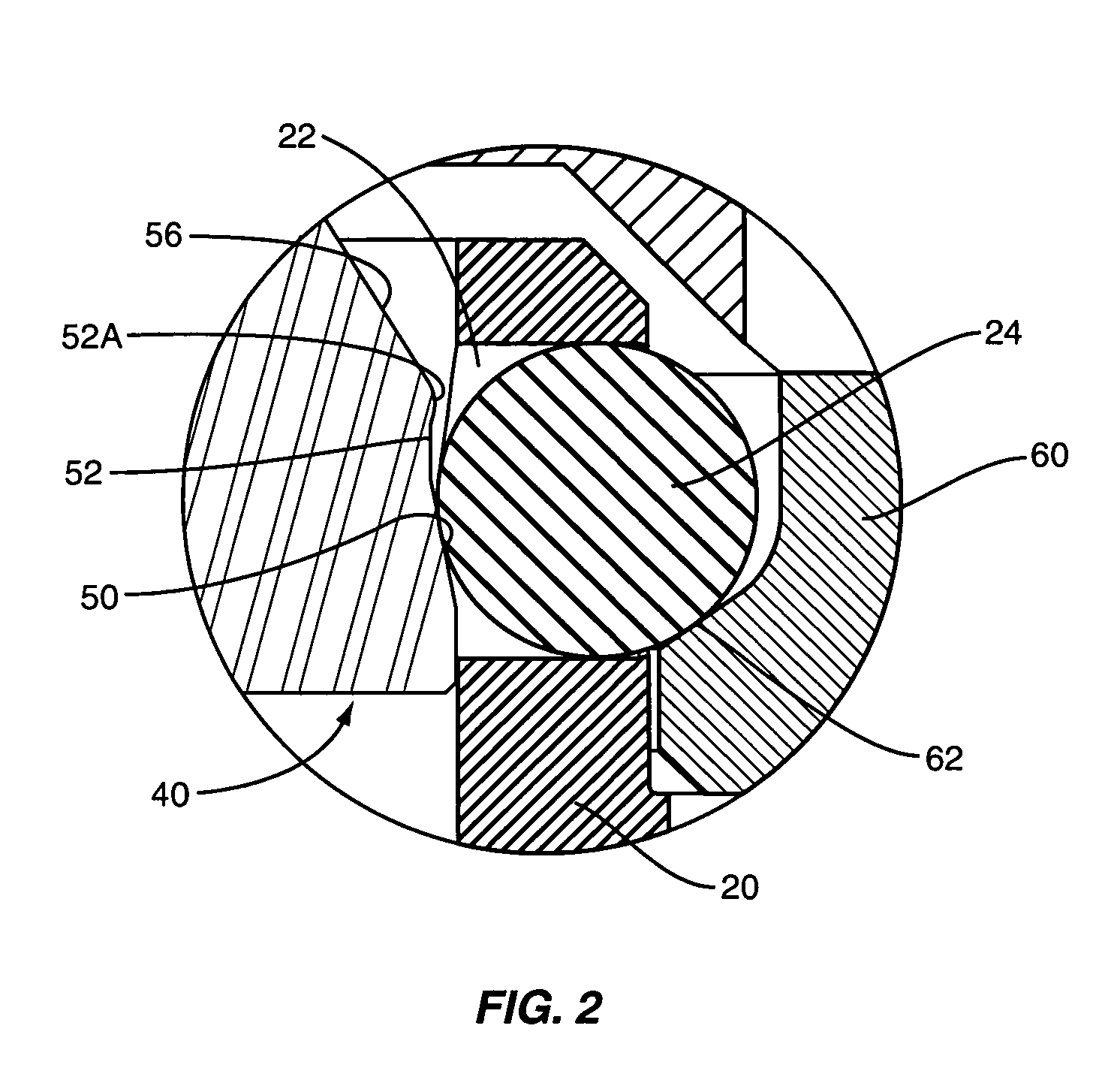
[0036]In FIGS. 8-11C, a second embodiment is shown for the contact area of the head 40 of the piston 30. In the embodiment shown in FIG. 1, the failsafe surface 52 comprised a ridge disposed between the locking surface 50 and the contact or unlocking surface 56. In this embodiment the failsafe surface 52 forms a generally conical shape surface between the locking surface 50 and the contact or unlocking surface 56. That is, as viewed in FIGS. 11A and 11B, the failsafe surface 52 extends upwardly and slightly outwardly to a point where the failsafe surface joins the contact or unlocking surface 56. If the failsafe surface 52 is projected downwardly around the piston 30, the projecting lines would form a cone. As seen in FIG. 11A, as the piston moves from the locked position shown in FIG. 8 to the unlocked position shown in FIG. 10, it is seen that the conical surface 52 retards the movement of the piston and gives rise to at least a slight resistance to the movement of the piston. Eff...

third embodiment

[0041]FIG. 12 illustrates the contact area of the piston head 40. In this case, the failsafe surface 52 includes two portions. First there is a generally cylindrical portion 52B and a second conical portion 52A. This design is similar to the embodiment shown in FIGS. 1-7B with the exception that the conical surface 52B assumes the position of the ridge in the embodiment of FIGS. 1-7B. In any event, in this embodiment, as the piston 30 moves from the locked position to the unlocked position, the rolling members will first engage the cylindrical portion 52B of the failsafe surface, and thereafter will engage the conical or angled surface 52B. Again, the conical or angled surface 52B will retard the movement of the piston 30 and prevent the piston 30 from inadvertently or accidentally moving past the conical or angled surface 52B to the unlocked position.

[0042]There are other ways to retard the movement of the piston from the failsafe position to the unlocked position. In FIG. 13 a por...


PUM

PropertyMeasurementUnit
angleaaaaaaaaaa
angleaaaaaaaaaa
retention areaaaaaaaaaaa

Abstract

A robotic tool changer having a master unit and a tool unit adapted to be coupled together. Movably mounted in the master unit of the robotic tool changer is a piston that is movable between locked and unlocked positions. The piston includes a contact area having an unlocking surface, a failsafe surface and a locking surface. Also provided is a series of rolling members contained within a retention area that are actuated by the piston to lock the master unit to the tool unit. For example, the piston engages the rolling members and urges them into a locked relationship with a bearing race that forms a part of the tool unit. To prevent the inadvertent or accidental movement of the piston from the locked position to the unlocked position, the piston is provided with a retarding surface generally disposed between the locking surface and the unlocking surface on the piston for retarding the movement of the piston as the piston moves from the locked position to the unlocked position.

Description

FIELD OF THE INVENTION[0001]The present invention relates to robotic tool changers, and more particularly to robotic tool changers having a master unit and a tool unit adapted to be coupled together.BACKGROUND OF THE INVENTION[0002]Robotic tool changers generally comprise a master unit and a tool unit. Typically the master unit is supported from a robotic arm while the tool unit is coupled to the master unit and supports a tool. In some designs, to couple the master and tool units together, the master unit is provided with a fluid actuated piston that includes a contact area for engaging a series of balls that are normally held in a ball retention area of the master unit. When the master unit and tool unit are engaged for connection, the contact area of the piston engages the ball and positions the balls outwardly where the balls engage a bearing race formed in the tool unit. The geometry of the bearing race and the manner of urging the balls into the bearing race causes the master ...

Claims


Application Information

Patent Timeline
Patent Type & Authority Patents(United States)
IPC IPC(8): G06F19/00
CPCB23B31/1071B23B31/30B25J15/04B23B2270/22Y10T403/591Y10T279/1045Y10T403/593Y10T403/22Y10T403/592
Inventor GLODEN, MICHAEL L.ODHAM, LEONARD AARONBORDEAUX, MARK D.
Owner ATI INDAL AUTOMATION
Why Eureka
Try Eureka