Self-aligning roller bearing with retainer and manufacturing method for self-aligning roller bearing retainer

a technology manufacturing methods, which is applied in the direction of rolling contact bearings, shafts and bearings, rotary bearings, etc., can solve the problems of inconvenient processing of inner rings, low flow rate of lubricant (lubrication oil) entering the above space, and high speed operation, so as to prevent disengagement of spherical rollers, reduce the cost of self-aligning roller bearings with retainers and keep the cost of inner rings

Active Publication Date: 2011-08-30
NSK LTD
View PDF18 Cites 16 Cited by
  • Summary
  • Abstract
  • Description
  • Claims
  • Application Information

AI Technical Summary

Benefits of technology

[0050]In a self-aligning roller bearing with retainer configured as described above, and a method of manufacturing the retainer for the self-aligning roller bearing, in the case of the self-aligning roller bearing with retainer according to the first aspect, the end sections of the column sections that are co-adjacent to each other in the circumferential direction, and that form the pockets, embrace respective spherical rollers and prevent disengagement of the spherical rollers from the pockets, in the axial direction of the outer ring and the inner ring. Therefore, it becomes unnecessary to form a rib section on an outer peripheral surface on both end sections in the axial direction of the inner ring, or to provide a connection section between the end sections of the column sections. As a result, an aperture area of the end section of the space between the inner peripheral surface of the outer ring and the outer peripheral surface of the inner ring can be made large. Moreover, this is advantageous from the aspect of high speed operation in the case where lubrication of rolling contact portions between rolling surfaces of the spherical rollers and the outer raceway and both inner raceways is to be carried out by means of splash lubrication, since the amount of lubrication (lubrication oil) that enters into the above space is increased. Furthermore, the rib sections do not have to be formed on both end sections in the axial direction of the outer peripheral surface of the inner ring. Hence the outer diameter of the inner ring can be made smallest at both end sections in the axial direction of the inner ring. Therefore the operation of assembling both retainers and the plurality of spherical rollers into the space between the outer peripheral surfaces of the inner ring and the inner peripheral surface of the outer ring, can be carried out easily. Furthermore, the processing operation of the inner ring becomes easier, thus keeping the cost of the self-aligning roller bearing with retainer including this inner ring low.
[0051]Moreover, in the case of the self-aligning roller bearing with retainer relating to the second aspect of the present invention, since the side surfaces in the circumferential direction of the column sections that divide both sides in the circumferential direction of the pockets are concave curved surfaces having a radius of curvature slightly greater than that of the rolling surface of the spherical rollers (by just the size of the pocket clearance), the orientation of the spherical rollers held in the pockets is stabilized. Therefore, significant skewing of the spherical rollers will not occur, and generation of significant sliding friction at the rolling contact portion between the rolling surfaces of the spherical rollers and the outer raceway and the inner raceways can be prevented. As a result, the resistance involved in the relative rotation between the outer ring and the inner ring, and vibration, that occur in operation, can be suppressed and high speed operation becomes possible.
[0052]Furthermore, according to the method of manufacturing a retainer for the self-aligning roller bearing of the present invention, the concave curved surface described above can be formed on the surfaces on both sides in the circumferential direction of the column sections with a high level of accuracy using an industrial technique that can be carried out at a comparatively low cost.
[0053]Moreover, in the case of the self-aligning roller bearing with retainer according to the third aspect of the present invention, when the retainer is displaced in the radial direction, the inside surface of the pockets of the retainer always makes contact with the end surface of the spherical rollers. Therefore, the radial direction position of the retainer is controlled by engagement of the inside surface of the pockets and the end surface of the spherical rollers. In the case of such an aspect of the invention, first, since the retainer is roller-guided, dynamic torque and heat generation due to operation of the self-aligning roller bearing with retainer can be reduced compared to the case of outer ring riding or inner ring riding. Furthermore, since there is no need for a floating guide ring, the number of parts is reduced.
[0054]Moreover, as described above, since the radial direction position of the retainer is controlled by engagement of the end surface of the spherical rollers and the inside surface of the pocket, even when the retainer has been displaced in the radial direction by its own weight, the distance from the end surface of the spherical rollers in the non-loaded zone to the inside surfaces of the retainer becomes shorter, and the occurrence of skewing in the spherical rollers in this non-loaded zone can be effectively suppressed. The reason that skewing can be suppressed by shortening the distance from the end surface of the spherical rollers to a surface opposing to this end surface in this way, is that the surface among the inside surfaces of the pockets that opposes the end surface is a plane surface (it does not have to be curved like the circumferential direction side surface of the column section). As long as the surface that contacts with the end surface of the spherical rollers is a plane surface, then, in the case where the spherical rollers are inclined such that skewing may occur and the end surface of the spherical rollers makes contact with the surface among the inside surfaces of the pocket that opposes to this end surface, it becomes easier to keep these spherical rollers from skewing further. Thus, if skewing is unlikely to occur to the spherical rollers, heat generation or vibration due to skew occurrence can be suppressed. As a result, a self-aligning roller bearing that is excellent at high speed can be achieved.
[0055]Furthermore, when a roller-guided configuration is employed, the friction speed of the engagement section for controlling the radial direction position of the retainer can be kept low, and dynamic torque and heat generation due to operation can be kept low.

Problems solved by technology

Consequently, in the case where lubrication of the rolling contact portion between the rolling surfaces of the spherical rollers 3 and the outer raceway 5 and both inner raceways 6 is to be carried out by means of splash lubrication with oil-mist or oil-air, there is a disadvantage from the aspect of performing high speed operation, as the flow rate of the lubricant (lubrication oil) that enters into the above space is decreased.
Therefore, a notch for passing through the respective spherical rollers 3 needs to be formed in one portion of both of the rib sections 10, making processing of the inner ring 2 inconvenient, and the effect of preventing coming off becomes imperfect.
Therefore, as is the case with the first, second, and fourth examples, the flow rate of lubricant (lubrication oil) that enters into the space decreases, resulting in a disadvantage for high speed operation.
This results in a greater amount of dynamic torque (rotational resistance) and heat being generated due to operation of the self-aligning roller bearing with retainer, which becomes a disadvantage in high speed operation.
Furthermore, there is a possibility of a greater amount of dynamic torque and heat being generated due to operation as a result of a difference in revolution speeds of both rows of spherical rollers 3.
As a result, as described above, there is a possibility of a greater amount of dynamic torque and heat being generated due to operation.
Moreover, in the cases of the first, third, and fourth examples of the conventional construction shown in FIG. 17, FIG. 21, and FIG. 22, since the retainers 4, 4b, and 4c for holding both rows of spherical rollers 3 are positioned by inner ring riding or outer ring riding, a disadvantage in achieving high speed operation of the rotation shaft arises from the following points.
This results in a greater amount of dynamic torque (rotational resistance) and heat being generated due to operation of the self-aligning roller bearing with retainer, which becomes a disadvantage in high speed operation.
However in the case of the self-aligning roller bearing with retainer, the retainer cannot be simply roller-guided for the following reason.
Consequently, skewing may become more likely to occur to the spherical rollers in the non-loaded zone depending on the status of their engagement with the inside surface of the pocket of the retainer.
Consequently, as the dynamic torque of the self-aligning roller bearing with retainer increases, the amount of heat generation increases, and furthermore, vibration occurring in the respective rolling contact portions becomes greater.
An increase in such dynamic torque and heat generation and the occurrence of vibration is disadvantageous for increasing the operation speed of the self-aligning roller bearing with retainer.
Therefore, the retainer that is assembled into the self-aligning roller bearing with retainer cannot be simply roller-guided.Patent Document 1: Japanese Patent Application Publication No.

Method used


Image

  • Self-aligning roller bearing with retainer and manufacturing method for self-aligning roller bearing retainer
  • Self-aligning roller bearing with retainer and manufacturing method for self-aligning roller bearing retainer
  • Self-aligning roller bearing with retainer and manufacturing method for self-aligning roller bearing retainer

Examples


Embodiment Construction

First Example of the Embodiment

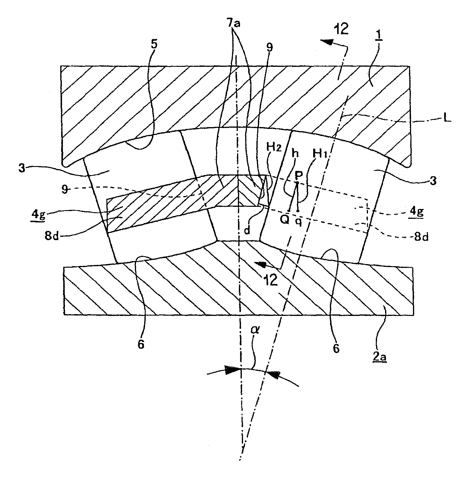
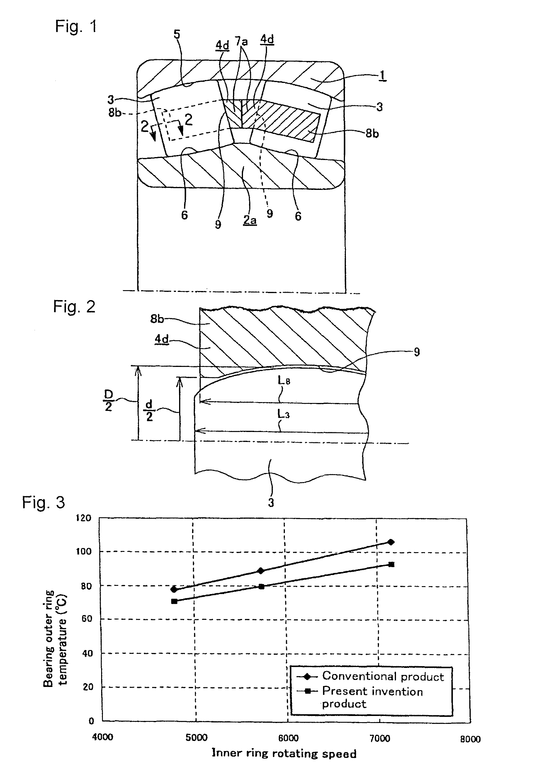
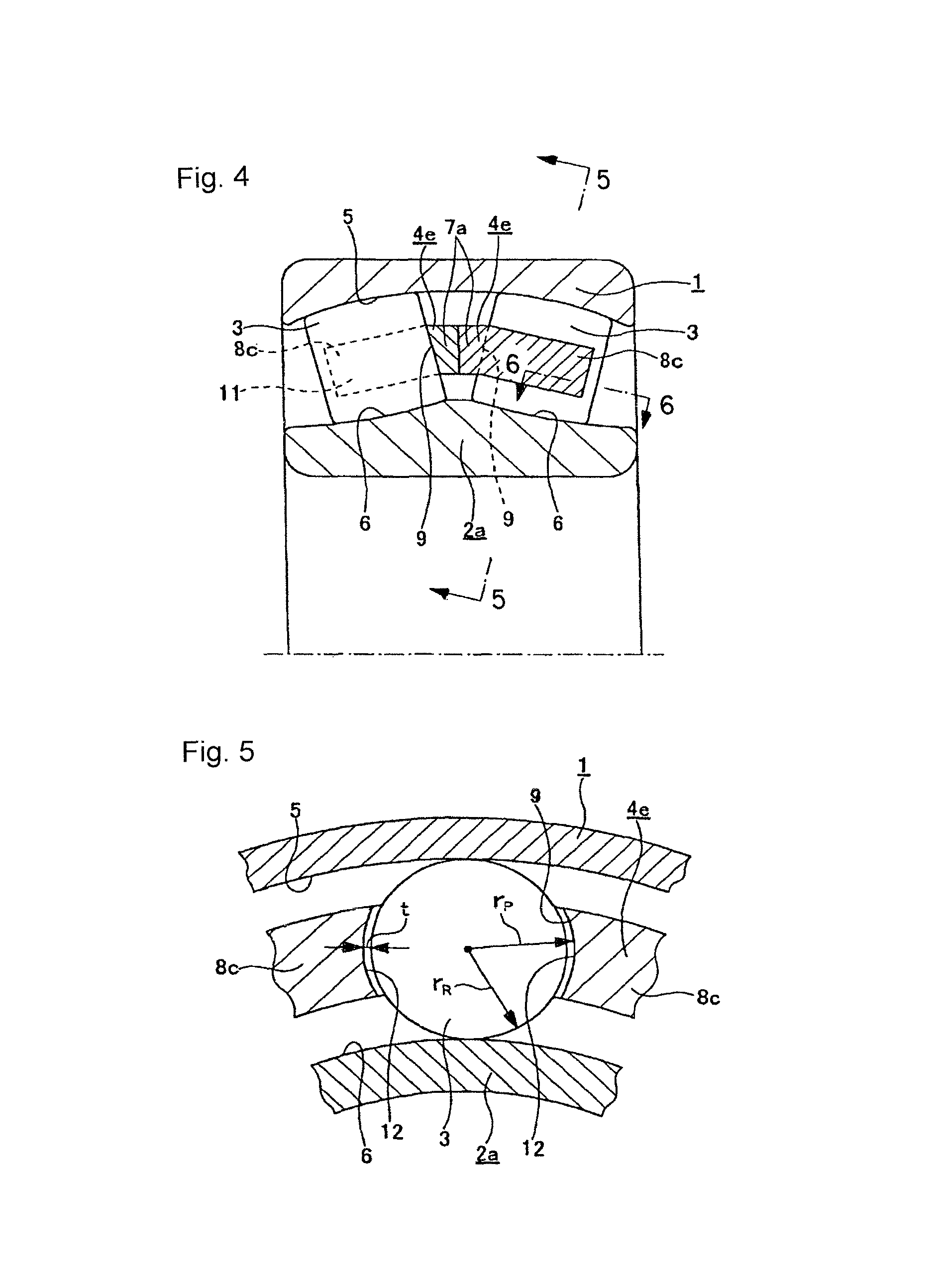
[0083]FIG. 1 to FIG. 2 show a first example of an embodiment of the present invention corresponding to a first aspect. A self-aligning roller bearing with a retainer of the present example comprises an outer ring 1, an inner ring 2a, a plurality of spherical rollers 3, and a pair of mutually independent (assembled rotatably with respect to one another) retainers 4d similar to the aforementioned second example of the conventional construction shown in FIG. 20.

[0084]The outer ring 1 has an inner peripheral surface upon which is formed a concave spherical outer raceway 5 having a single center.

[0085]Moreover, on an outer peripheral surface of the inner ring 2a a pair of inner raceways 6 are formed so as to oppose the above outer raceway 5. Unlike the case of the aforementioned second example of the conventional construction, there are no rib sections 10 (refer to FIG. 20) provided on both ends of the outer peripheral surface of this inner ring 2a. The inn...


PUM


Abstract

There is realized a self-aligning roller bearing with retainer that stabilizes the orientation of spherical rollers and prevents these spherical rollers from skewing, and which can be rotated at high speed, and furthermore which enables efficient lubricant feed into pockets 9. By rotating a turning tool 14 as it revolves, the surfaces on both sides in the circumferential direction of respective column sections are processed into concave curved surfaces that oppose a rolling surface of the respective spherical rollers across a pocket clearance into which lubricant oil can be fed. The length of the column sections 8c is less than the length in the axial direction of the spherical rollers, and greater than a half of the length, and an end portion of the side surface in the circumferential direction of the respective column sections 8c projects further in the circumferential direction than an intermediate portion thereof, and the spherical rollers are embraced in the pockets 9.

Description

TECHNICAL FIELD[0001]A self-aligning roller bearing with retainer relating to the present invention is used for example assembled into a rotation supporting section of a roller shaft of various kinds of industrial mechanical apparatuses such as a paper manufacturing machine and a metal rolling mill, for supporting a rotation shaft inside a housing.BACKGROUND ART[0002]For example, for supporting a heavy shaft inside a housing so that it may rotate freely, a self-aligning roller bearing with retainer such as for example, those disclosed in Japanese Patent Application Publication No. H 09-317760 (Patent Document 1) and in Japanese Utility Model Registration No. 2524932 (Patent Document 2), has conventionally been used. FIG. 16 to FIG. 19 show a first example of the conventional construction disclosed in Patent Document 1. This self-aligning roller bearing with retainer is configured with a plurality of spherical rollers 3 arranged so as to allow them to rotate freely between an outer r...

Claims


Application Information

Patent Timeline
Patent Type & Authority Patents(United States)
IPC IPC(8): F16C23/08F16C33/49
CPCF16C19/38F16C23/086F16C33/48F16C33/485F16C33/497F16C33/4676
Inventor MURAI, TAKASHITANAKA, TOSHIYUKIICHIMARU, MASATAKE
Owner NSK LTD
Why Eureka
Try Eureka