Fuel cell stack

a fuel cell and stack technology, applied in the field of fuel cell stacks, can solve the problems of short-circuiting of separators and degrading the sealing performance of fuel cells, and achieve the effect of simple structure and reliably preventing short-circuiting or degradation of sealing performan

Active Publication Date: 2011-08-30
HONDA MOTOR CO LTD
View PDF7 Cites 3 Cited by
  • Summary
  • Abstract
  • Description
  • Claims
  • Application Information

AI Technical Summary

Benefits of technology

[0010]A main object of the present invention is to provide a fuel cell stack having a simple structure, which makes it possible to reliably prevent degradation in sealing performance or short-circuiting of the separators due to deformation thereof, when an external load is applied to the fuel cell stack.
[0013]In this manner, it is possible to suitably prevent degradation in sealing performance due to displacement of the fuel cell itself, and moreover, short-circuiting of the separators does not occur. Further, when assembling the fuel cell, since the resin guide section disposed at the outer end of at least one of the separators slides along a guide, compared to the case in which all of the separators slide, sliding resistance is reduced and the assembly operation can be performed easily.

Problems solved by technology

Under these circumstances, for example, if an external load is applied to the vehicle, and the casing becomes deformed in a manner so as to contact the separators, short-circuiting of the separators may occur.
In addition, the separators may become deformed, thus degrading the sealing performance of the fuel cells.

Method used


Image

  • Fuel cell stack
  • Fuel cell stack
  • Fuel cell stack

Examples


first embodiment

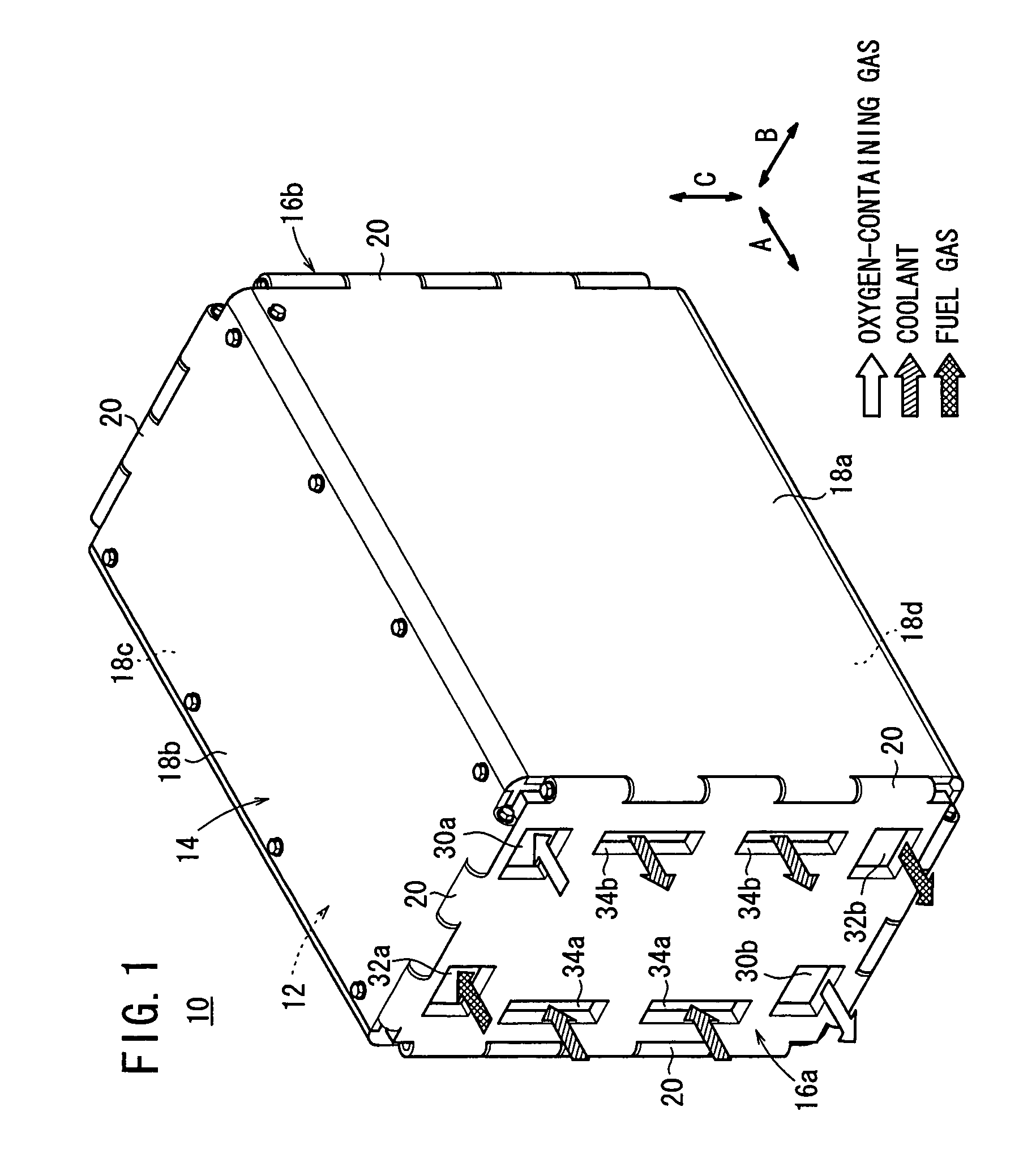
[0028]FIG. 1 is a perspective view showing a fuel cell stack 10 according to the present invention.

[0029]The fuel cell stack 10 is formed by stacking a plurality of fuel cell units 12 in a casing 14, in the direction indicated by the arrow A. The casing 14 includes end plates 16a, 16b provided at opposite ends of the fuel cell unit 12 in the stacking direction, four side plates 18a to 18d provided on sides of the fuel cell unit 12, and hinge mechanisms 20 for coupling the end plates 16a, 16b and the side plates 18a to 18d together.

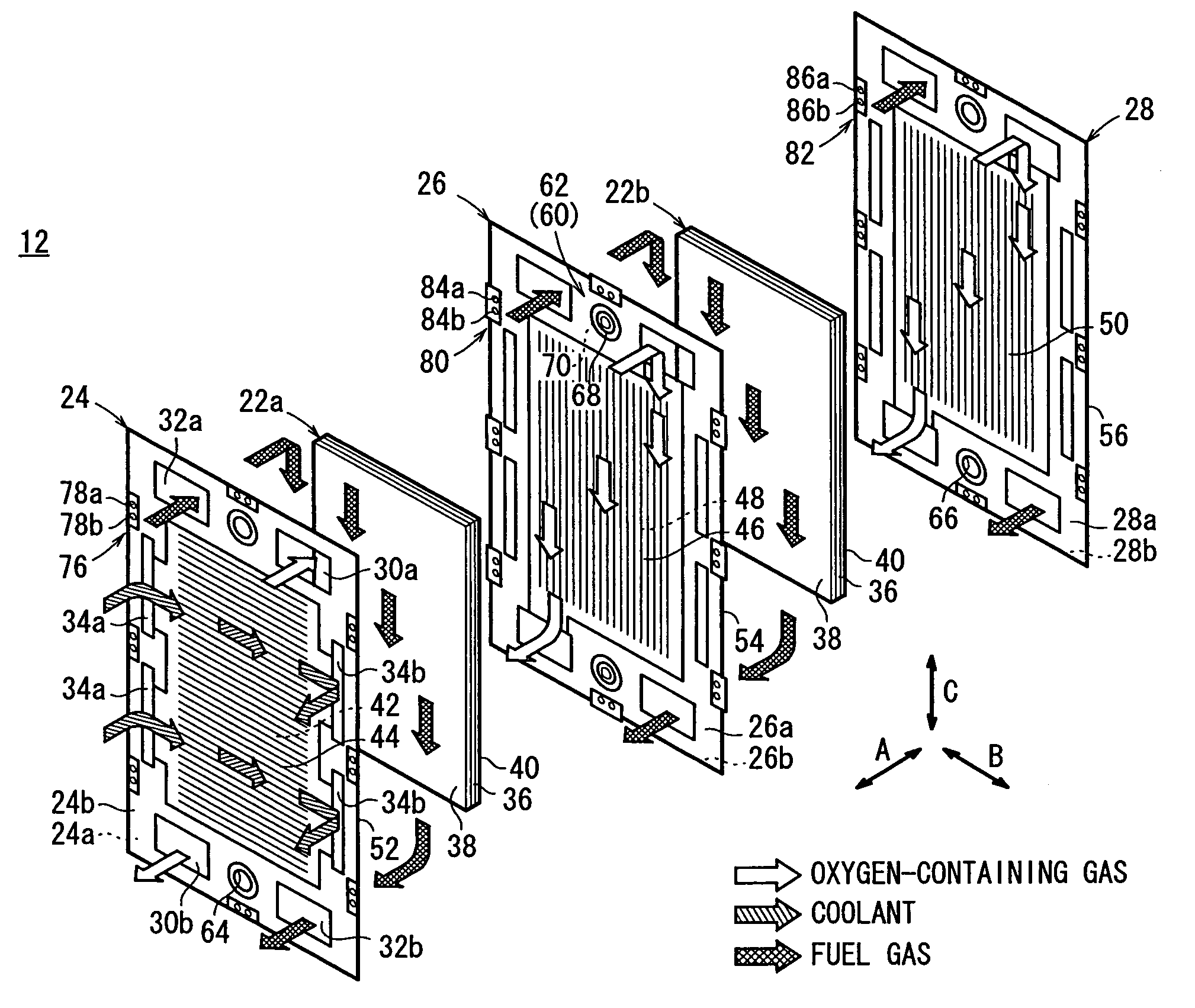
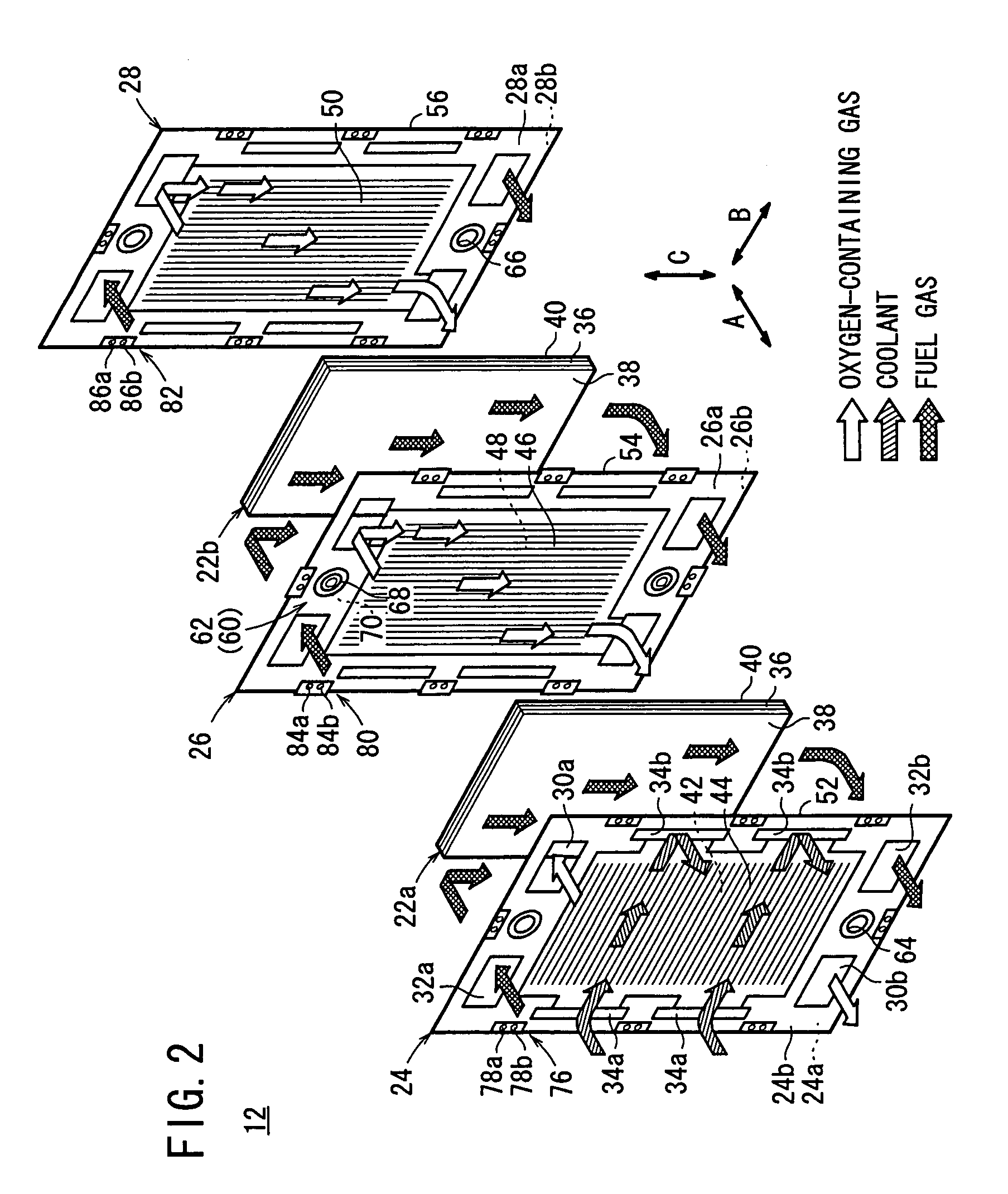
[0030]As shown in FIG. 2, the fuel cell unit 12 includes at least a first membrane (electrolyte) electrode assembly 22a and a second membrane electrode assembly 22b, along with at least a first separator 24, a second separator 26, and a third separator 28. The first membrane electrode assembly 22a is sandwiched between the first separator 24 and the second separator 26. The second membrane electrode assembly 22b is sandwiched between the second separator 2...

second embodiment

[0075]In the second embodiment, since the resin clips 102 have the slits 104 therein, the resin clips 102 have a certain elasticity. Therefore, when an external load F is applied to the resin clip 102 through the load receiver 80, the resin clip 102 is deformed elastically through the slits 104, whereby the external load F can be absorbed.

[0076]In this structure, the resin clip 102 has both a load absorption function and a load distribution function, for distributing the load to the first separator 24, the second separator 26, and the third separator 28. Therefore, it is possible to further reliably prevent displacement or sealing failure of the fuel cell unit 12.

third embodiment

[0077]FIG. 9 is an enlarged cross sectional view showing principal components of a fuel cell stack 110 according to the present invention.

[0078]Load receivers 112, 114, 116 are disposed integrally with the first separator 24, the second separator 26, and the third separator 28, of each fuel cell unit 12. The load receivers 114 of the second separator 26 protrude outwardly beyond the load receivers 112, 116. As shown in FIGS. 9 and 10, a plurality of small holes (apertures) 118 are formed at front ends of the load receivers 112, 114 and 116.

[0079]Resin clips 102 (or 88) are inserted into the load receivers 112, 114, 116 in order to fix the first separator 24, the second separator 26, and the third separator 28 together.

[0080]In the third embodiment, as shown in FIG. 9, an external load is applied to the casing 14. As a result, when the side plate 18a is deformed internally and comes into contact with inner front ends of the load receivers 114, owing to the presence of the small holes...


PUM

PropertyMeasurementUnit
shapeaaaaaaaaaa
elasticityaaaaaaaaaa
timeaaaaaaaaaa

Abstract

Each of the fuel cell units making up a fuel cell stack includes a first separator, a second separator, and a third separator. A predetermined number of load receivers are provided integrally on outer ends of the first separator, the second separator, and the third separator. The load receivers of the second separator protrude toward the casing beyond the other load receivers. Resin clips are inserted into the load receivers, such that the first separator, the second separator, and the third separator are fixed together by the resin clips.

Description

BACKGROUND OF THE INVENTION[0001]1. Field of the Invention[0002]The present invention relates to a fuel cell stack formed by stacking fuel cells, each including an electrolyte electrode assembly and separators. The electrolyte electrode assembly includes a pair of electrodes, with an electrolyte interposed between the electrodes.[0003]2. Description of the Related Art[0004]For example, a polymer electrolyte fuel cell employs a membrane electrode assembly (electrolyte electrode assembly), which includes an anode, a cathode, and an electrolyte membrane interposed between the anode and the cathode. The electrolyte membrane is a solid polymer ion exchange membrane. The membrane electrode assembly and separators sandwiching the membrane electrode assembly therebetween make up a fuel cell.[0005]Normally, several tens to hundreds of fuel cells are stacked together to form a fuel cell stack. It is necessary to accurately position the components of the fuel cell, while maintaining the fuel c...

Claims


Application Information

Patent Timeline
Patent Type & Authority Patents(United States)
IPC IPC(8): H01M2/00H01M8/24
CPCH01M8/2475H01M8/248H01M2008/1095Y02E60/50
Inventor SAKANO, MASAAKIANDOU, KEISUKE
Owner HONDA MOTOR CO LTD
Why Eureka
Try Eureka