
Vacuum insulated switchgear

a vacuum-insulated switch and switch body technology, applied in the direction of switchgear arrangements, contact mechanisms, contact forms, etc., can solve the problem that the insulated busbars in phases cannot be disposed side by sid

Inactive Publication Date: 2011-08-30
HITACHI LTD
View PDF9 Cites 8 Cited by
  • Summary
  • Abstract
  • Description
  • Claims
  • Application Information

AI Technical Summary

Benefits of technology

This configuration allows for the connection of insulated busbars between compartments without interference, enabling flexible alignment and reducing the need for special molds or height adjustments, thus providing a cost-effective and safe installation method.

Problems solved by technology

This poses a problem in that insulated busbars in phases cannot be disposed side by side in the width direction of each compartment.

Method used


Image

  • Vacuum insulated switchgear
  • Vacuum insulated switchgear
  • Vacuum insulated switchgear

Examples


Embodiment Construction

[0030]The vacuum insulated switchgear of the embodiment in the present invention will be described below with reference to the drawings.

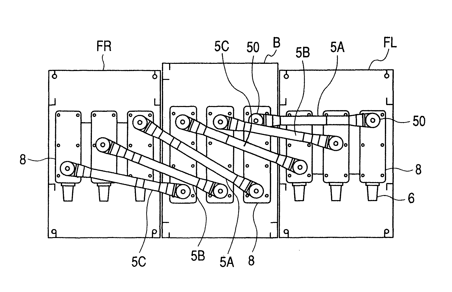
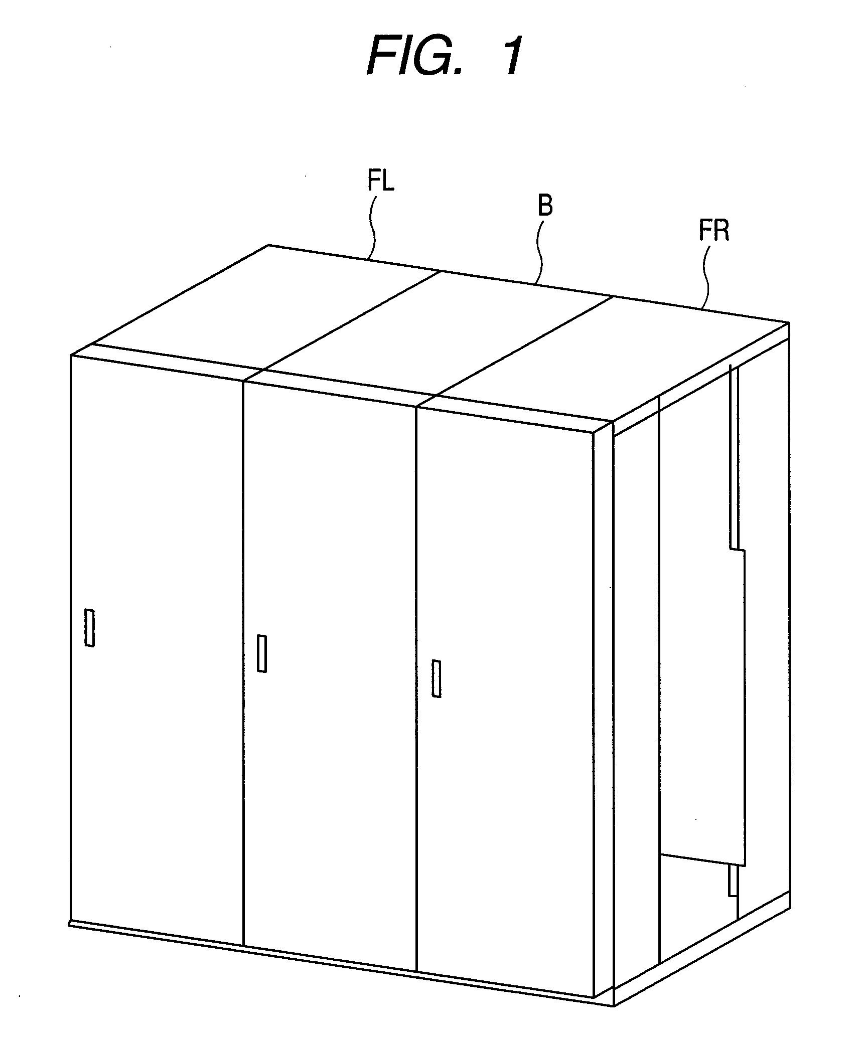
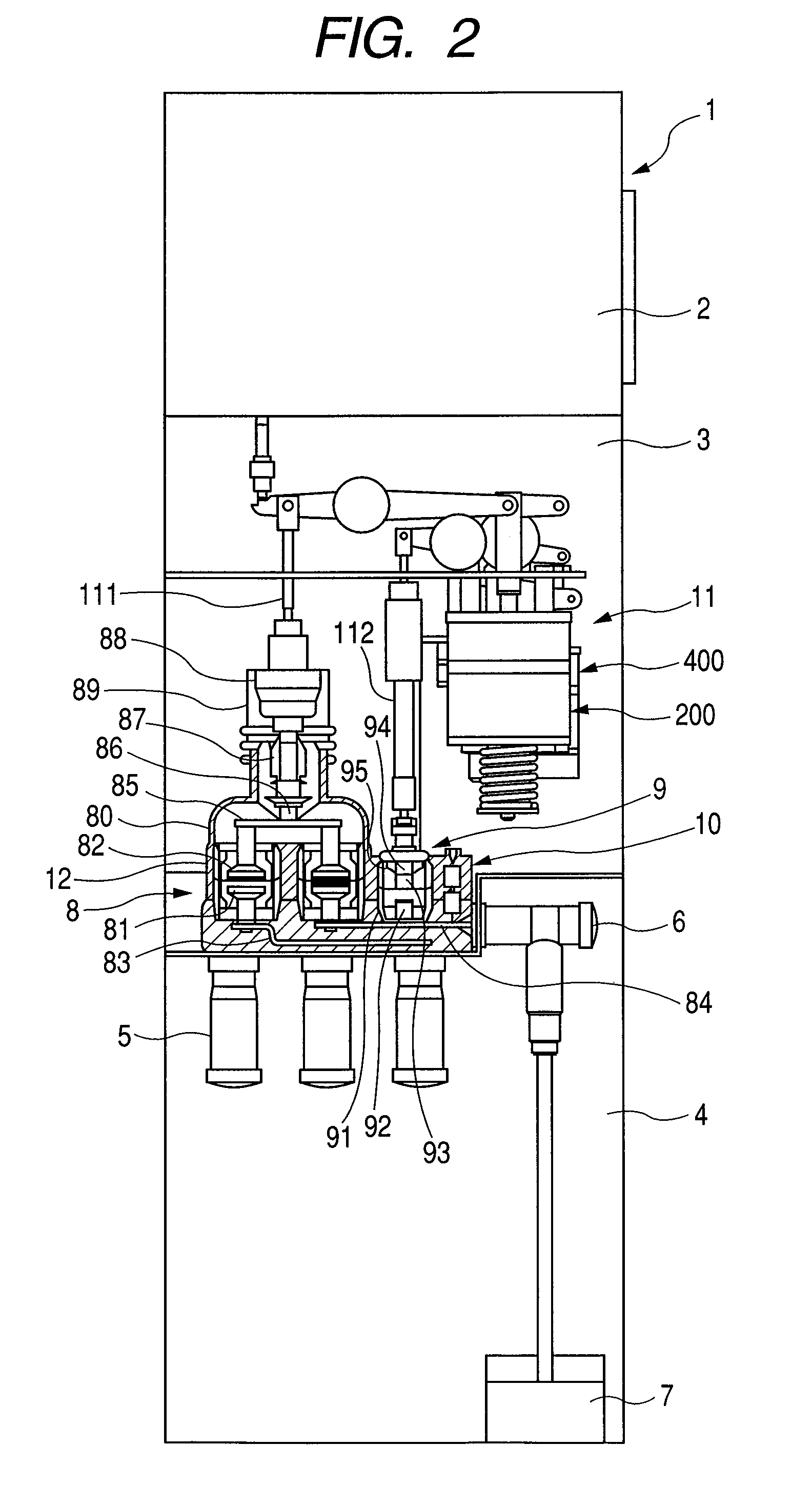
[0031]FIGS. 1 to 6 illustrate an embodiment of the vacuum insulated switchgear in the present invention. FIG. 1 is a perspective view of the vacuum insulated switchgear, which embodies the present invention, in which a busbar compartment and feeder compartments are aligned in a row. FIG. 2 is a vertical sectional view of the vacuum insulated switchgear shown in FIG. 1. FIG. 3 is a front view of one feeder compartment of the vacuum insulated switchgear shown in FIG. 1. FIG. 4 is a vertical sectional view of the busbar compartment of the vacuum insulated switchgear shown in FIG. 1. FIG. 5 is a rear view of the vacuum insulated switchgear shown in FIG. 1. FIG. 6 is a bottom plan view of the vacuum insulated switchgear shown in FIG. 5.

[0032]In FIG. 1, the vacuum insulated switchgear, which embodies the present invention, comprises a busbar compartment B...


PUM


Abstract

A vacuum insulated switchgear has a busbar compartment, in which phase-segregated double-break, three-position vacuum circuit breakers are disposed; and feeder compartments disposed at both sides of the busbar compartment respectively, in each of which phase-segregated double-break, three-position vacuum circuit breakers are disposed. The busbar compartment and the feeder compartments are aligned in a row, and a second-phase insulated busbar is provided to connect one of the fixed contacts of a second-phase breaker in the busbar compartment to a fixed contact of a second-phase breaker in one of the feeder compartments. A first-phase insulated busbar is provided to connect one of the fixed contacts of a first-phase breaker in the busbar compartment to a fixed contact of a first-phase breaker in one of the feeder compartments adjacent to the busbar compartment, and the second-phase insulated busbar and the first-phase insulated busbar are disposed in different positions in height.

Description

CLAIM OF PRIORITY[0001]The present application claims priority from Japanese patent application JP 2007-185510 filed on Jul. 17, 2007, the content of which is hereby incorporated by reference into this application.BACKGROUND OF THE INVENTION[0002]1. Field of the Invention[0003]The present invention relates to a small, lightweight vacuum insulated switchgear with high reliability and performance and, more particularly, to a vacuum insulated switchgear that enables a busbar compartment and feeder compartments to be connected through insulated busbars.[0004]2. Description of Related Art[0005]In a power receiving facility, a closed electric panel (referred to below as a switchgear) is installed, which houses vacuum breakers for shutting down a current to a load or a fault current, disconnecting switches and earthing switches, which are used to ensure safety for operators who service and inspect the load, detecting units for detecting a system voltage and current, protective relays, and ...

Claims


Application Information

Patent Timeline
Patent Type & Authority Patents(United States)
IPC IPC(8): H01H33/66
CPCH01H33/6606H01H33/666H02B13/0354H02B13/005H01H2239/044H01H2203/036
Inventor KUROGI, TAKUYATSUCHIYA, KENJISUGAI, DAISUKE
Owner HITACHI LTD
Learn More