Supercharge Your Innovation With Domain-Expert AI Agents!

Electronic access control handle set for a door lock

a technology of electronic access control and lever set, which is applied in the direction of mechanical control devices, limiting/preventing/returning movement of parts, keyhole guards, etc., can solve the problems of unauthorized users, large disadvantages, and expensive and inconvenient business, and achieve the effect of increasing torqu

Active Publication Date: 2011-09-06
SIMONSVOSS TECH
View PDF116 Cites 39 Cited by
  • Summary
  • Abstract
  • Description
  • Claims
  • Application Information

AI Technical Summary

Benefits of technology

"The present invention provides a handle set for a door lock with a latch that can be retrofitted into existing door locks to turn them into electronic locks. The handle set has an authenticator circuit and actuator protected from tampering. The handle set is designed to allow the exterior handle to transfer force to a coupling apparatus without transmitting large amounts of force to the blocking member when the blocking member is in the coupled position. The invention also provides a coupling cartridge for an electronic lock with an exterior handle, interior handle, lock body with latch, and access control circuit. The coupling cartridge is designed to handle increased torque transmitted by a lever without damaging a low-power actuator. The invention also provides a security apparatus to prevent the blocking member from moving to a position between the camming blocks and from a position between the camming blocks so that the electronic lock cannot change between coupled and decoupled states unless authorized to do so. The invention also provides a coupling cartridge with a plurality of handing marks that allows for untrained personnel to hand the electronic lock. The invention also provides a method of handing a coupling cartridge with a coupling member, interior handle linkage, and exterior handle linkage that allows for easy alignment between the markings."

Problems solved by technology

Although key-operated locking mechanical systems may provide adequate protection in most situations, there are some drawbacks associated with their use.
Firstly, keys for the most part can be easily copied and distributed to unauthorized users.
Also, if the key is ever lost or stolen, it might be necessary to replace the whole lock cylinder in order to assure that an unauthorized user does not gain access.
This can be a significant disadvantage in some cases.
For example, it could be costly and rather inconvenient for a business location having many employees to replace a lock cylinder each time an employee loses his key.
Although the deadbolt offers security against prying, one of the disadvantages of this locking system is that the electronic access control means can be accessed from the outside, and thus can be tampered with.
If the access control means are located on the inside of the door, an expensive through connection is necessary, which is dependent on the type of door and lock and which is furthermore difficult to install.
Known coupling interface devices and methods of this kind prove to be disadvantageous in that relatively much energy is demanded for shifting the coupling or lock element that forces acting on the coupling element in the coupled and decoupled states and causes a load of the lock element and that a load of the coupling element or lock element is transmitted to the drive or actuator.
In the decoupled state, the coupling locking element is not positioned between the reels, and the reels cannot overcome the mechanical potential of the take-off.
The coupling interface and / or actuator may not be configured to handle the stress of the forces exerted by the user, especially when excessive force is exerted through a lever.
The transmission of forces to the drive or actuator can result in increased wear and reduced functional safety.
In the United States, building codes may require that locks have levers, and levers can transmit large amounts of torque to a lock.
Low-energy electronic lock mechanisms may not be strong enough to handle the torque from a lever without breaking or wearing down.
Locks are typically installed by carpenters or other building tradesmen with no special locksmith training so that even the partial disassembly and reassembly of the intricate components by such personnel to“hand” the lock results in a maximum of frustration, limited success, and added expense.
The alternate choice of engaging a locksmith to install the lock adds considerable expense.
Electronic door locks may be susceptible to tampering, especially when the lock circuitry and / or actuator are / is located within the exterior handle.
It can also be difficult to provide electronic lock hardware that mechanically interacts with existing conventional door locks, and it can be especially difficult to provide electronic lock hardware that can be retrofitted into installed / mounted conventional door locks.

Method used


Image

  • Electronic access control handle set for a door lock
  • Electronic access control handle set for a door lock
  • Electronic access control handle set for a door lock

Examples


Embodiment Construction

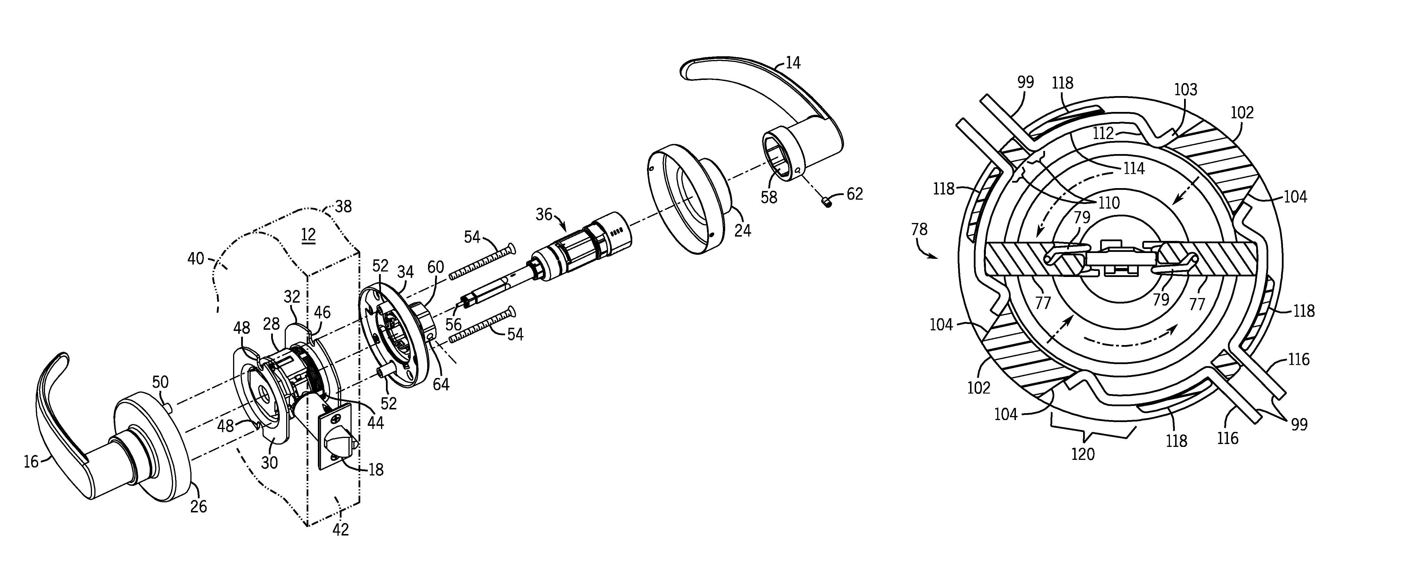
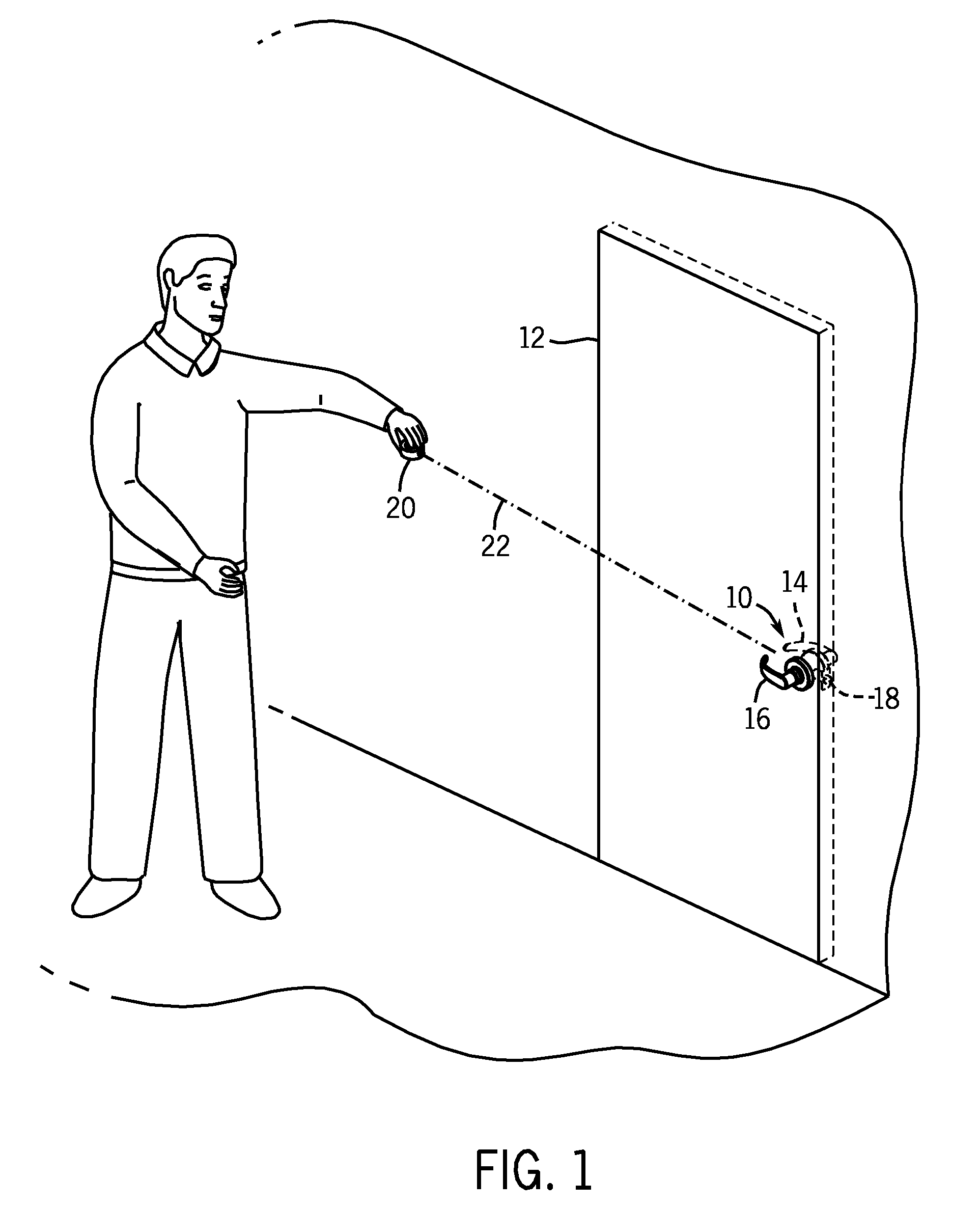
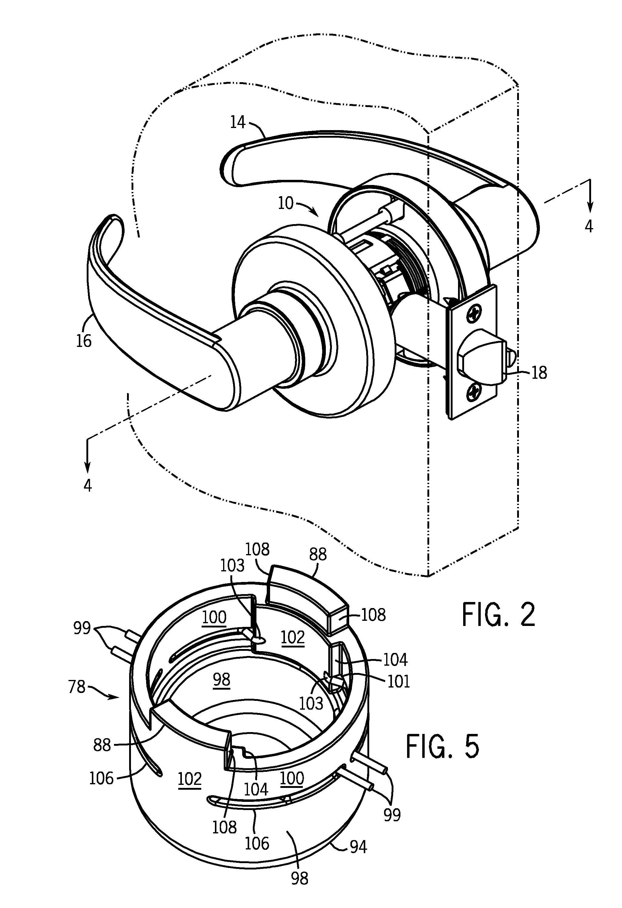
[0057]One or more specific embodiments of the present invention will be described below. It is specifically intended that the present invention not be limited to the embodiments and illustrations contained herein, but include modified forms of those embodiments including portions of the embodiments and combinations of elements of different embodiments as come within the scope of the following claims. It should be appreciated that in the development of any such actual implementation, as in any engineering or design project, numerous implementation-specific decisions must be made to achieve the developers' specific goals, such as compliance with system-related and business related constraints, which may vary from one implementation to another. Moreover, it should be appreciated that such a development effort might be complex and time consuming, but would nevertheless be a routine undertaking of design, fabrication, and manufacture for those of ordinary skill having the benefit of this...


PUM


Abstract

The present invention provides for a handle set for a lock with a latch, the handle set having an authentication circuit and actuator in the interior handle that allow access to authenticated transponders. The present invention also provides a device and method for transmitting a rotational movement and force in an electronic lock, wherein the transmission takes place in a coupled state and not in a decoupled state and wherein the transmission of force does not damage an actuator that requires little energy to change between the coupled and decoupled states. The handle set can include a coupling cartridge that can be easily handed. The electronic lock can be retrofitted in installed mortise locks and used with cylindrical locks. The electronic lock can include a security feature that prohibits the electronic lock from changing between the coupled and decoupled states.

Description

CROSS-REFERENCE TO RELATED APPLICATIONS[0001]This application is a continuation-in-part of application Ser. No. 10 / 726,260, filed Dec. 2, 2003, which claims priority to German Application No. 103 20 873.9, filed May 9, 2003, and which is a continuation-in-part of application Ser. No. 10 / 705,021, filed Nov. 11, 2003, now abandoned, which claims priority to German Application No. 103 20 873.9, filed May 9, 2003, and this application is also a continuation-in-part of application Ser. No. 10 / 556,012, which is a national stage of International Application No. PCT / EP2004 / 004903, filed May 7, 2004, which claims priority to German Application No. 103 20 873.9, filed May 9, 2003, the contents of which are hereby incorporated by reference as if fully set forth herein; and this application also claims the benefit of U.S. Provisional Application No. 60 / 744,268, filed Apr. 4, 2006, and entitled “Handel Set for a Door Lock,” the contents of which are hereby incorporated by reference as if fully s...

Claims


Application Information

Patent Timeline
Patent Type & Authority Patents(United States)
IPC IPC(8): E05B55/04B60R25/04
CPCE05B47/0011E05B47/0692E05B3/02E05B47/0006E05B63/04E05B63/16E05B2047/0092E05B15/0033Y10T70/5823Y10T70/713Y10T292/82Y10T70/542Y10T70/7107Y10T70/5496Y10T70/7102
Inventor MARSCHALEK, JAMES SSIMONSEN, WARREN A.VOSS, LUDGERMEYERLE, HERBERTVOSS, NORBERTPARHOFER, STEFAN
Owner SIMONSVOSS TECH
Features
  • R&D
  • Intellectual Property
  • Life Sciences
  • Materials
  • Tech Scout
  • Unparalleled Data Quality
  • Higher Quality Content
  • 60% Fewer Hallucinations
Learn More