Punching apparatus

a technology of a punching apparatus and a sleeve, which is applied in the direction of stock shearing machines, metal-working machine components, manufacturing tools, etc., can solve the problems of uneven cuts and structural fractures, hard and more brittle than warm cellular pvc, and significant breakage along the shearing lin

Active Publication Date: 2011-09-06
JAIN AMERICA HLDG INC
View PDF11 Cites 14 Cited by
  • Summary
  • Abstract
  • Description
  • Claims
  • Application Information

AI Technical Summary

Benefits of technology

[0008]The foregoing needs have been satisfied by the development of a unique rotary type slot punching apparatus of extreme speed, precision and robustness that incorporates unique and innovative cellular PVC processing techniques such as special tooling design and coatings and electrostatic charge abatement. More particularly, the present invention incorporates a unique approach to siding slot punching by utilizing two opposed, precision, counter-rotating wheels: the upper wheel having punches and the lower wheel having a series of mating dies complementary to the punches in the upper wheel. These punches and their mating dies incorporate cutting edges on the entire periphery of the slot shape thereby providing full shearing of the entire slot including the ends.

Problems solved by technology

The geometry of this conventional arrangement shears the slot sides but does not perform actual punch / die shearing of the slot ends.
The material has been cured and is therefore harder and more brittle than warm cellular PVC.
Profiled cellular PVC boards punched with the above described conventional arrangement, show significant breakage along the shear line, uneven cuts and structural fractures in the slot vicinity due to not fully shearing the entire slot.
Therefore, the conventional slot punching arrangement is totally inadequate for forming slots in cellular PVC boards.
Additionally, specially contoured and coated tooling is required when punching cellular PVC material due to its highly abrasive qualities, as compared to conventional vinyl siding material.

Method used


Image

  • Punching apparatus
  • Punching apparatus
  • Punching apparatus

Examples


Embodiment Construction

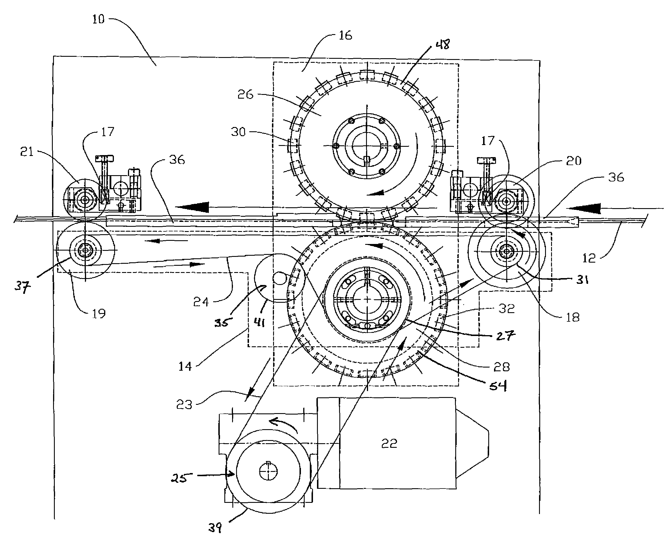
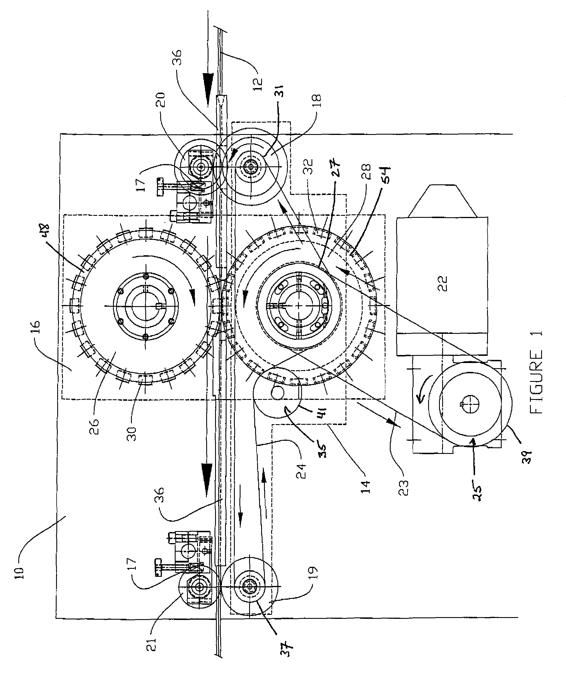
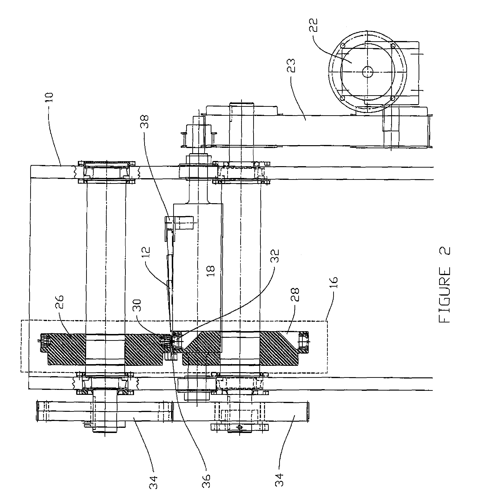
[0013]The punching apparatus of the present invention forms slots in boards, wherein an exemplary use of the slotted boards is as siding material. Although the boards may comprise a variety of materials, in an especially preferred embodiment the board comprises cellular PVC. The inventive punching apparatus offers a novel approach for the formation of slots in the nailing flange area of the board, wherein the punching apparatus is designed to shear all of the exposed sides of the slot, and not merely just the slot's lateral sides as is done in conventional punching operations. To accomplish this, the inventive punching apparatus comprises a plurality of punches disposed about a frame of an upper wheel. Each of the punches forming the plurality comprise a shearing portion that extends from the frame, and which is configured to fit within a cavity of a respective mating die located on a lower wheel. The shearing portion comprises a geometrical shape and size to match that of the desir...


PUM

PropertyMeasurementUnit
diameteraaaaaaaaaa
shapeaaaaaaaaaa
speedaaaaaaaaaa

Abstract

A punching apparatus for forming a series of slots in a board, comprising: an upper wheel and a lower wheel, wherein the upper wheel is opposed to the lower wheel, and further wherein: the upper wheel comprises a series of punches disposed on a frame of the upper wheel, wherein each punch comprises a shearing portion that extends from the frame, and which is configured in the shape of a slot; and the lower wheel comprises a series of mating dies, wherein each mating die of the series of mating dies comprises a cavity, wherein the shearing portion of a particular punch is gradually disposed within the cavity of a particular mating die of the series of mating dies as the upper wheel and the lower wheel move in relation to each other.

Description

CROSS REFERENCE TO RELATED APPLICATIONS[0001]This application claims the benefit of U.S. Provisional Application No. 60 / 747,629 filed on May 18, 2006.BACKGROUND OF THE INVENTION[0002]1. Field of the Invention[0003]The present invention is generally related to an apparatus for punching. More particularly, this invention is related to an apparatus for punching slots into profiled cellular polyvinylchloride (cellular PVC) boards, wherein an exemplary application of such punched, profiled cellular PVC is in the use as siding.[0004]2. Background of the Invention[0005]This invention relates to a novel apparatus for punching slots into profiled cellular PVC boards to be used as siding. Slot punching of cellular PVC boards at the required production throughput rate demands an entirely unique approach to achieve the required slot punching accuracy as compared to prior art punching apparatuses used to punch traditionally used rigid vinyl siding materials.[0006]Conventional high speed rigid ro...

Claims


Application Information

Patent Timeline
Patent Type & Authority Patents(United States)
IPC IPC(8): B23D25/02B23D15/00
CPCB26F1/10B26D3/10B26F1/384B26F1/44Y10T83/6668Y10T83/2096Y10T83/6625Y10T83/6649Y10T83/2196Y10T83/0515
Inventor LOPER, THOMAS
Owner JAIN AMERICA HLDG INC
Why Eureka
Try Eureka