
Temperature-controlled magnetic resonance imaging method and apparatus

a magnetic resonance imaging and temperature control technology, applied in the field of temperature-controlled magnetic resonance imaging (mri) equipment, can solve the problems of large temperature coefficient, significant temperature increase, deterioration of imaging quality, etc., and achieve the effect of accurate and more synchronously

Inactive Publication Date: 2011-09-06
SIEMENS HEALTHCARE GMBH
View PDF3 Cites 3 Cited by
  • Summary
  • Abstract
  • Description
  • Claims
  • Application Information

AI Technical Summary

Benefits of technology

This approach effectively synchronizes temperature regulation and compensates for imaging quality deterioration factors, improving MRI image quality by accurately predicting and adjusting for temperature and frequency fluctuations caused by the gradient system's heating effects.

Problems solved by technology

A disadvantage of this type of magnet is its very large temperature coefficient, which is sensitive to temperature changes.
When the temperature of the magnets changes, it will cause the homogeneity of the magnetic field within an imaging field of view to deteriorate and thus lead to field drifting; according to the Larmor equation, the field drifting will directly cause frequency drifting, thereby leading to deterioration of the imaging quality.
However, when the MRI equipment is operated continuously to execute the MRI sequences for a long time (for example, several hours), its gradient system will produce a heating effect, which causes significant temperature increase (i.e., causing substantial temperature drifting) in the magnets.
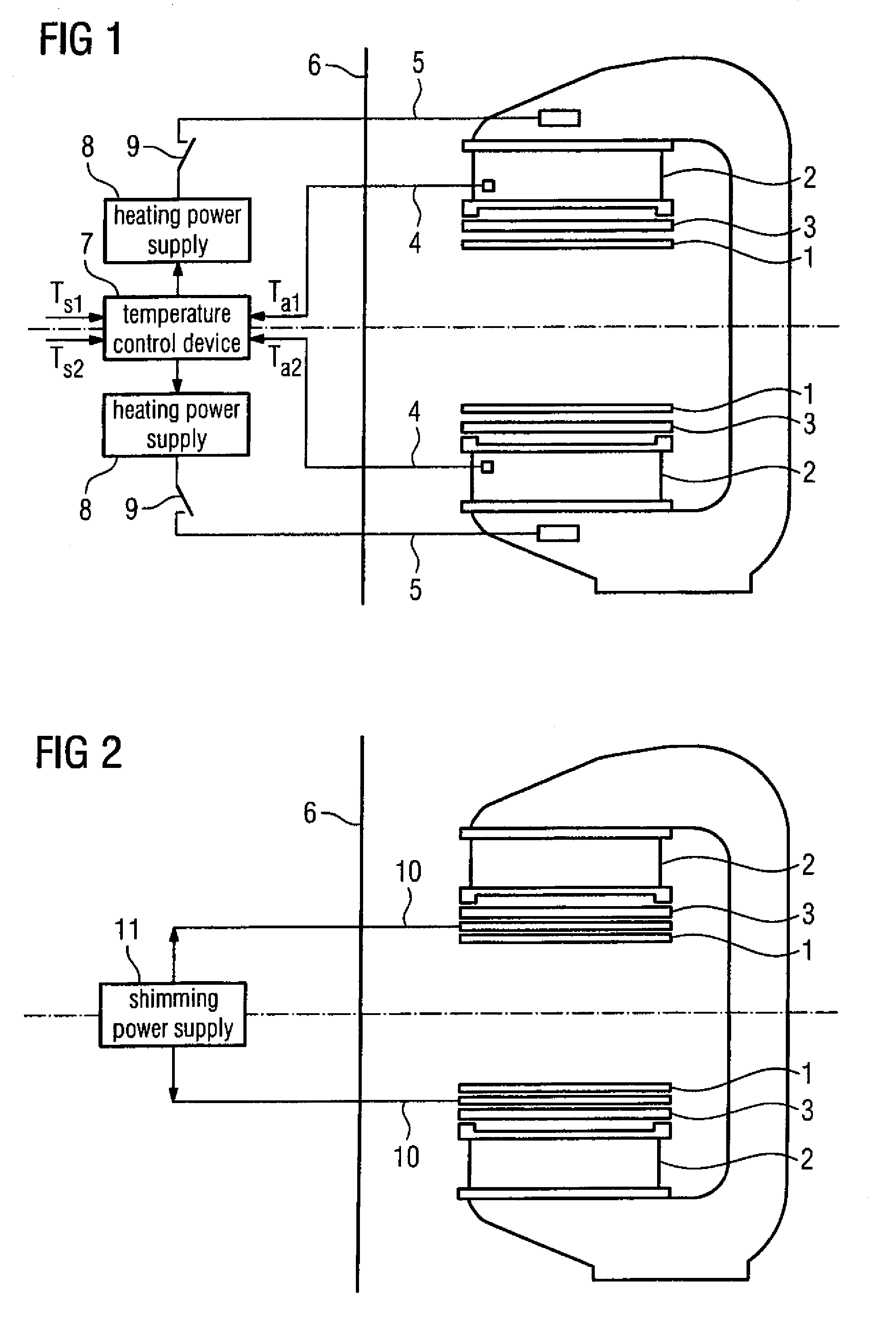
However, since the magnet 2 is a huge thermal sink, it is difficult for the PID parameter of aforementioned technical solution to guarantee the synchronization between the regulation of output power and the temperature variations when MRI scanning sequences are running continuously, phenomena such as hysteresis, advance, oscillation, etc., will inevitably exist.
Furthermore, the regulation period of the solution is long, allowing substantial temperature fluctuation to exist in the magnets.
Therefore it is difficult to achieve the purpose of improving imaging quality.
This solution is high in costs and complicated in its regulation, furthermore, it is difficult to dynamically compensate the field drifting generated during the sequence scanning.
Therefore it is difficult to achieve the goal of improving imaging quality.
It can be seen from the above description that, in the currently available technical solutions there are respective shortcomings in improving the imaging quality of MRI equipment, and it is difficult for either approach to achieve the goal of improving the imaging quality.

Method used


Image

  • Temperature-controlled magnetic resonance imaging method and apparatus
  • Temperature-controlled magnetic resonance imaging method and apparatus
  • Temperature-controlled magnetic resonance imaging method and apparatus

Examples


embodiment one

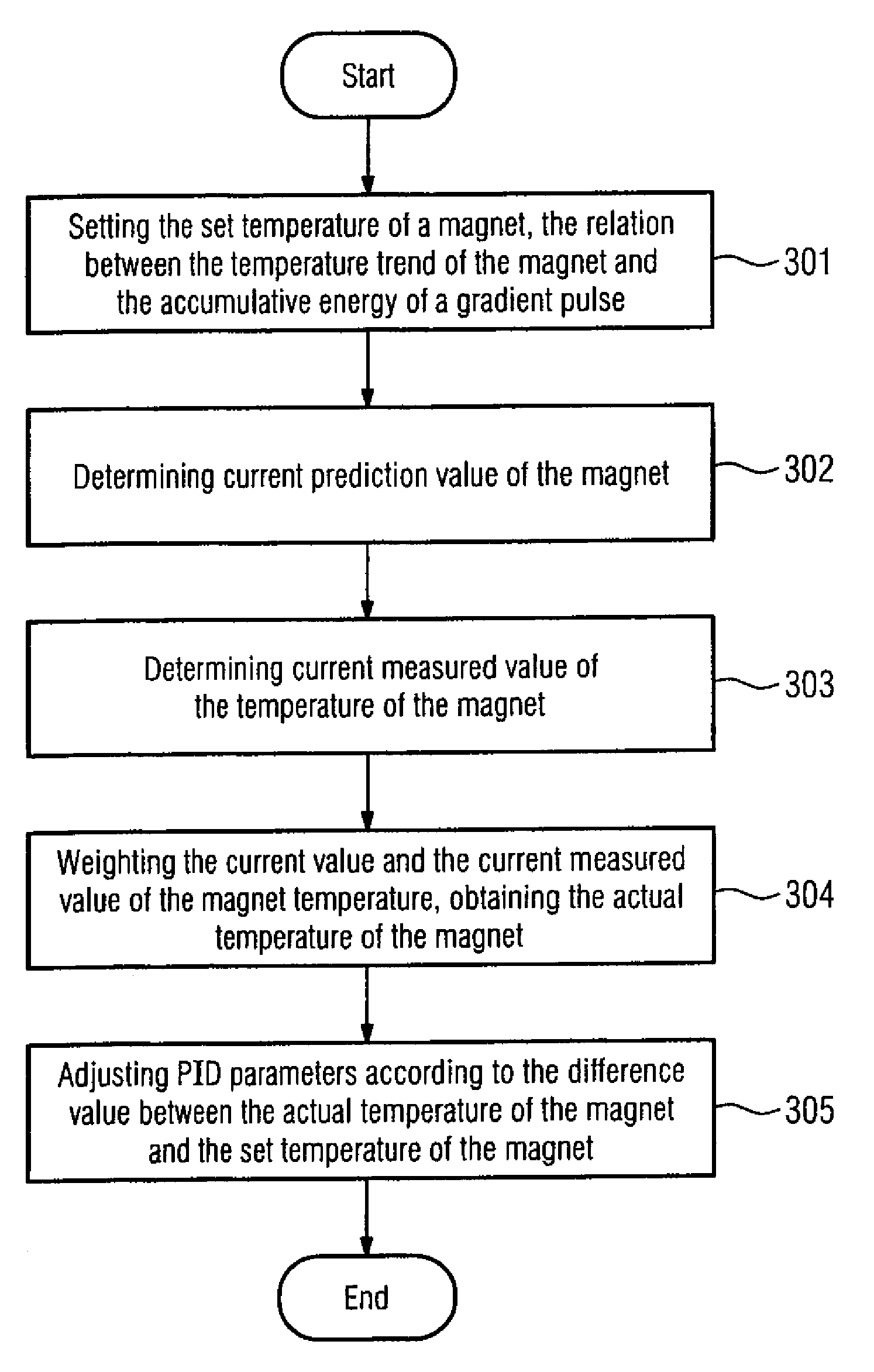
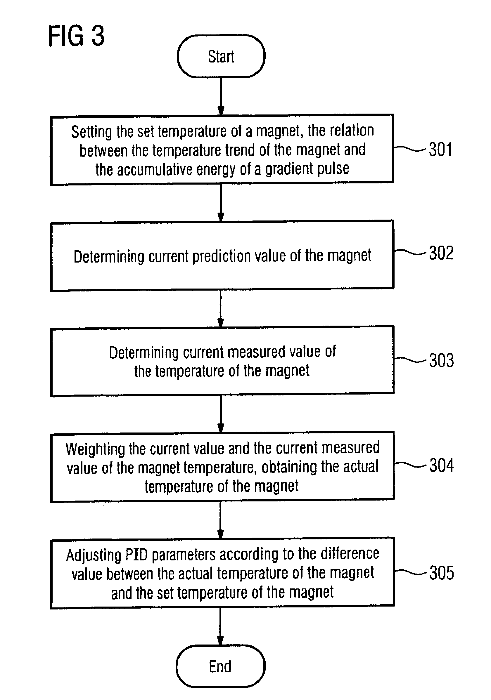
[0061]This embodiment provides a technical solution in keeping the temperature of a magnet constant by use of the correlation between the magnet temperature drifting trend and the cumulative energy of gradient pulses.

[0062]FIG. 3 is the schematic flowchart of the method of the first embodiment of the present invention for improving the imaging quality of MRI equipment. Referring to FIG. 3, the method comprises:

[0063]Step 301: presetting the set temperature of the magnet in a temperature control device, and presetting the corresponding relationship between the magnet temperature drifting trend of the magnet used in the MRI equipment for imaging and the cumulative energy of gradient pulses.

[0064]In this step, it can set respectively the set temperature of an upper magnet and the set temperature of a lower magnet, and, the corresponding relationship between the set magnet temperature drifting trend and the cumulative energy of gradient pulses can comprise: the corresponding relationshi...

embodiment two

[0119]This embodiment provides a technical solution for dynamically filtering the frequency drifting interference in MRI signals by use of the correlation of the frequency drifting interference of MRI signals within the imaging field of view and the cumulative energy of gradient pulses.

[0120]FIG. 6 is a flowchart of the method for improving the imaging quality of MRI equipment in the second embodiment of the present invention. Referring to FIG. 6, the method includes the following steps.

[0121]Step 601: presetting the corresponding relationship between the frequency drifting interference of MRI equipment within the imaging field of view and the cumulative energy of gradient pulses.

[0122]Before performing the setting in this step 601, many experiments can be carried out, and, by experimental results the corresponding relationship between the frequency drifting interference of MRI signals within the imaging field of view and the cumulative energy of gradient pulses is determined.

[0123]...


PUM


Abstract

A method for improving the imaging quality of magnetic resonance imaging (MRI) equipment and MRI equipment, include obtaining a corresponding relationship between a deterioration factor of imaging quality and the cumulative energy of gradient pulses applied by successive scanning MRI sequences, then determining a predicted value of a current deterioration factor of imaging quality according to the currently applied cumulative energy of the gradient pulses and said corresponding relationship, adopting a corresponding method to carry out dynamic regulation or compensation using the predicted value of said deterioration factor of imaging quality as a reference, so as to cancel the influence produced by the heating effect of the gradient system to the imaging quality, thereby effectively improving the imaging quality of the MRI equipment.

Description

BACKGROUND OF THE INVENTION[0001]1. Field of the Invention[0002]The present invention relates to the technology of magnetic resonance imaging (MRI) equipment, and particularly to a method for improving the imaging quality of MRI equipment and MRI equipment.[0003]2. Description of the Prior Art[0004]MRI equipment is used to execute magnetic resonance (MR) sequences for obtaining corresponding images. The magnets of MRI equipment, especially of permanent magnetic MRI equipment, for generating the basic magnetic field are generally made of rare earth materials of high magnetic permeability, such as neodymium, iron, boron, etc. A disadvantage of this type of magnet is its very large temperature coefficient, which is sensitive to temperature changes. When the temperature of the magnets changes, it will cause the homogeneity of the magnetic field within an imaging field of view to deteriorate and thus lead to field drifting; according to the Larmor equation, the field drifting will direct...

Claims


Application Information

Patent Timeline
Patent Type & Authority Patents(United States)
IPC IPC(8): G01V3/00
CPCG01R33/383G01R33/385G01R33/3856G01R33/3804
Inventor CHEN, LI MINGXUE, TING QIANGWANG, JIAN MIN
Owner SIEMENS HEALTHCARE GMBH
Learn More