
Electronic blasting capsule

a technology of electronic blasting and capsules, applied in the direction of ammunition fuzes, lighting and heating equipment, borehole/well accessories, etc., can solve the problems of limited energy transfer quantity of energy to the energy input device, per cycle of external energy sources,

Inactive Publication Date: 2011-09-13
SANDVIK MINING & CONSTR RSA (PTY) LTD
View PDF11 Cites 30 Cited by
  • Summary
  • Abstract
  • Description
  • Claims
  • Application Information

AI Technical Summary

Benefits of technology

The solution provides a reliable and safe initiation mechanism for the blasting capsule, ensuring it is only fired at the correct position and time, enhancing operational safety and reducing the risk of unintended detonation.

Problems solved by technology

Preferably the quantity of energy which is transferred to the energy input device, per cycle of the external energy source, is limited.

Method used


Image

  • Electronic blasting capsule
  • Electronic blasting capsule
  • Electronic blasting capsule

Examples


Embodiment Construction

[0027]The present invention is described in the context of the disclosure in the specification of international patent application number PCT / ZA2006 / 000037 the content of which is hereby incorporated, to the extent which may be necessary for an understanding of the present invention, into this specification. Although the present invention is described in the context of the aforegoing international patent specification it is to be understood that this is by way of example only and is non-limiting. Thus the principles of the invention can be used in other applications.

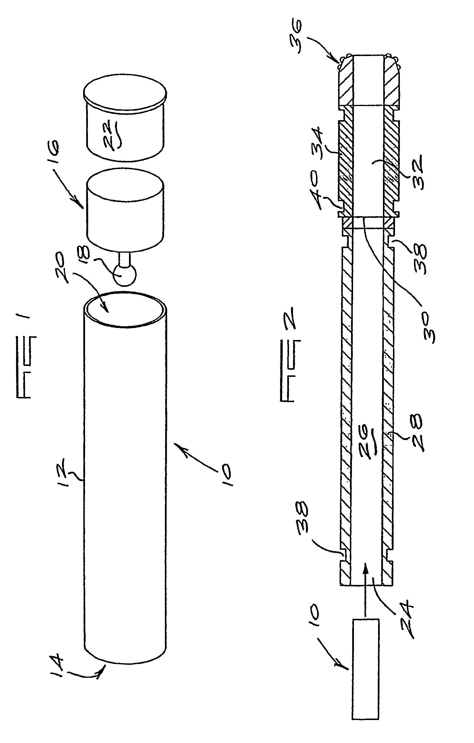
[0028]In the invention described in the specification of the international application a rock drill is used to drill a hole in a rock face. A propellant cartridge is then fed along a cartridge delivery path which extends from a cartridge magazine along a passage inside a drill shank into a passage inside a drill bit. The cartridge is caused to move by water flow. The water flow rate is high and the cartridge is caused to...


PUM


Abstract

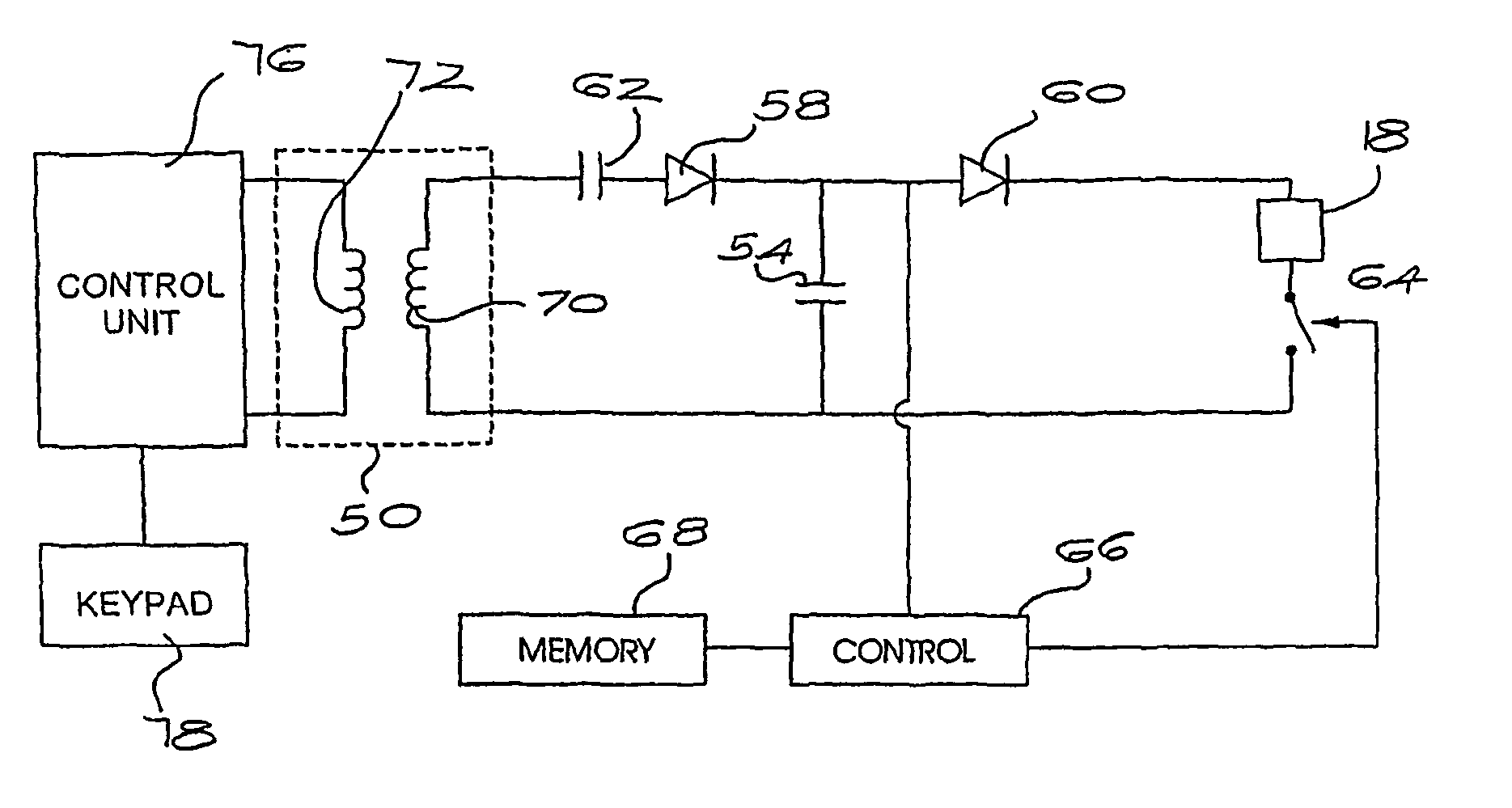
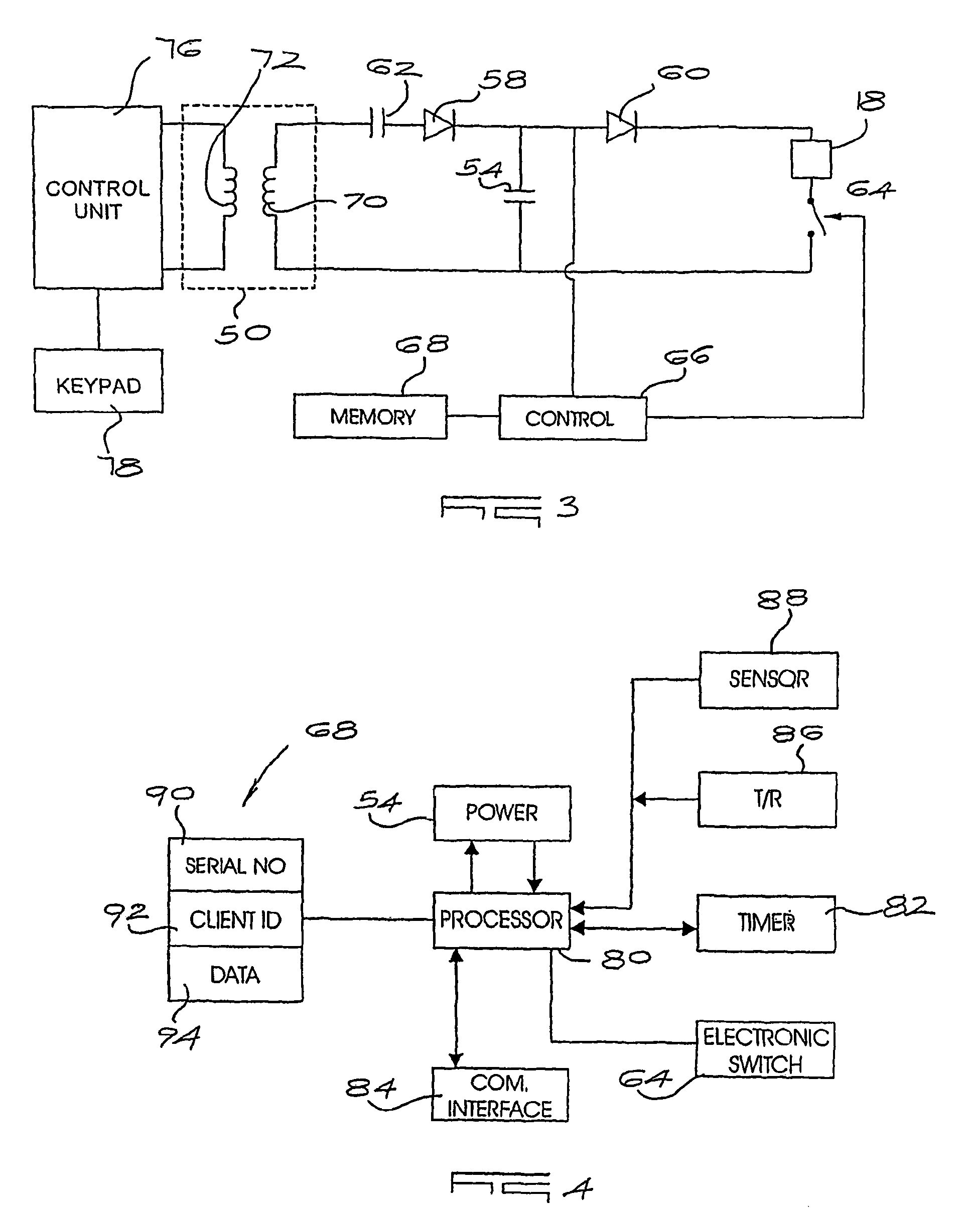
An electronic blasting capsule which includes a housing which contains a propellant, a fuse, a sensor for detecting the position of the housing in a capsule delivery path, an energy arrangement for obtaining energy from an external energy source, and a controller, responsive to the sensor and the energy arrangement, for firing the fuse to initiate the propellant.

Description

CROSS-REFERENCE TO RELATED APPLICATIONS[0001]This is a U.S. National Phase of International Application PCT / ZA2008 / 000080, filed Sep. 8, 2008, and claims the benefit of priority under 35 U.S.C. §119 based on South African Application No. 2007 / 08012, filed Sep. 10, 2007, the entire disclosures of which applications are hereby incorporated herein by reference.BACKGROUND OF THE INVENTION[0002]This invention relates to an electronic blasting capsule.[0003]The specification of international patent application number PCT / ZA2006 / 000037 describes a drilling machine which uses a drill bit, attached to a drill rod, to drill a hole in a rock face. The drill rod and drill bit are left in situ in the hole and a pressurised source is used to direct a propellant cartridge along passages in the drill rod and drill bit. In one situation the cartridge is ignited by causing the cartridge to impact against a wall of the hole. This can be somewhat unreliable.[0004]It is known in the technology field whi...

Claims


Application Information

Patent Timeline
Patent Type & Authority Patents(United States)
IPC IPC(8): F42B3/00F42B3/10F42D3/04
CPCE21B43/1185F42D3/04F42B3/00
Inventor LEPPANEN, JARMOOOSTHUIZEN, OCKERT
Owner SANDVIK MINING & CONSTR RSA (PTY) LTD
Learn More