Pattern formation device

a technology of pattern formation and pattern, which is applied in the direction of closed-circuit television systems, coatings, television systems, etc., can solve the problems of inability to obtain uniform discharge quantity, difficulty in feeding down-flow to the area, and further heating so as to reduce the number of component parts, and suppress the effect of temperature increase of droplet discharge heads

Inactive Publication Date: 2011-09-20
TOKYO ELECTRON LTD
View PDF6 Cites 0 Cited by
  • Summary
  • Abstract
  • Description
  • Claims
  • Application Information

AI Technical Summary

Benefits of technology

[0010]The present invention was developed in order to overcome the above-mentioned problems, and an object of the present invention is to provide a pattern formation device in which the air around the carriage is expelled, and in which the area around the carriage is simplified.
[0027]Since the air introduced to the area around the carriage from the area around the droplet discharge device does not flow between the droplet discharge head and the substrate, correct landing positioning of the droplets can be ensured.

Problems solved by technology

This structure therefore makes it difficult for a down-flow to be fed to the area around the carriages and droplet discharge heads.
In other words, air that is heated by the heat of the droplet discharge heads stagnates in the area around the carriages, which leads to further heating of the droplet discharge heads, and a uniform discharge quantity is impossible to obtain.
However, in the method disclosed in the above mentioned reference, the horizontally directed air flow enters the space between the droplet discharge heads and the substrate and diverts the path of the droplets discharged from the droplet discharge heads, and there is a risk of not being able to land the droplets in the correct positions.
An exhaust-dedicated duct may also be placed in the area around the carriages as a method for expelling the air around the carriages, but this method is difficult to implement when the maintenance space of the carriages is considered.

Method used


Image

  • Pattern formation device
  • Pattern formation device
  • Pattern formation device

Examples


first embodiment

[0036]An embodiment of the pattern formation device in which the present invention is implemented will be described below according to the drawings.

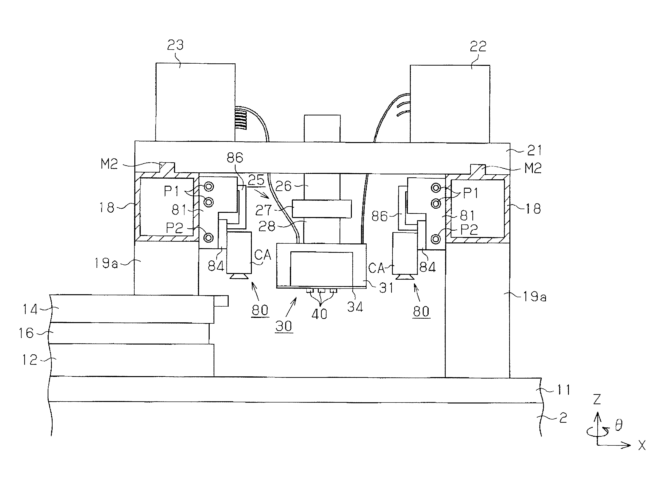
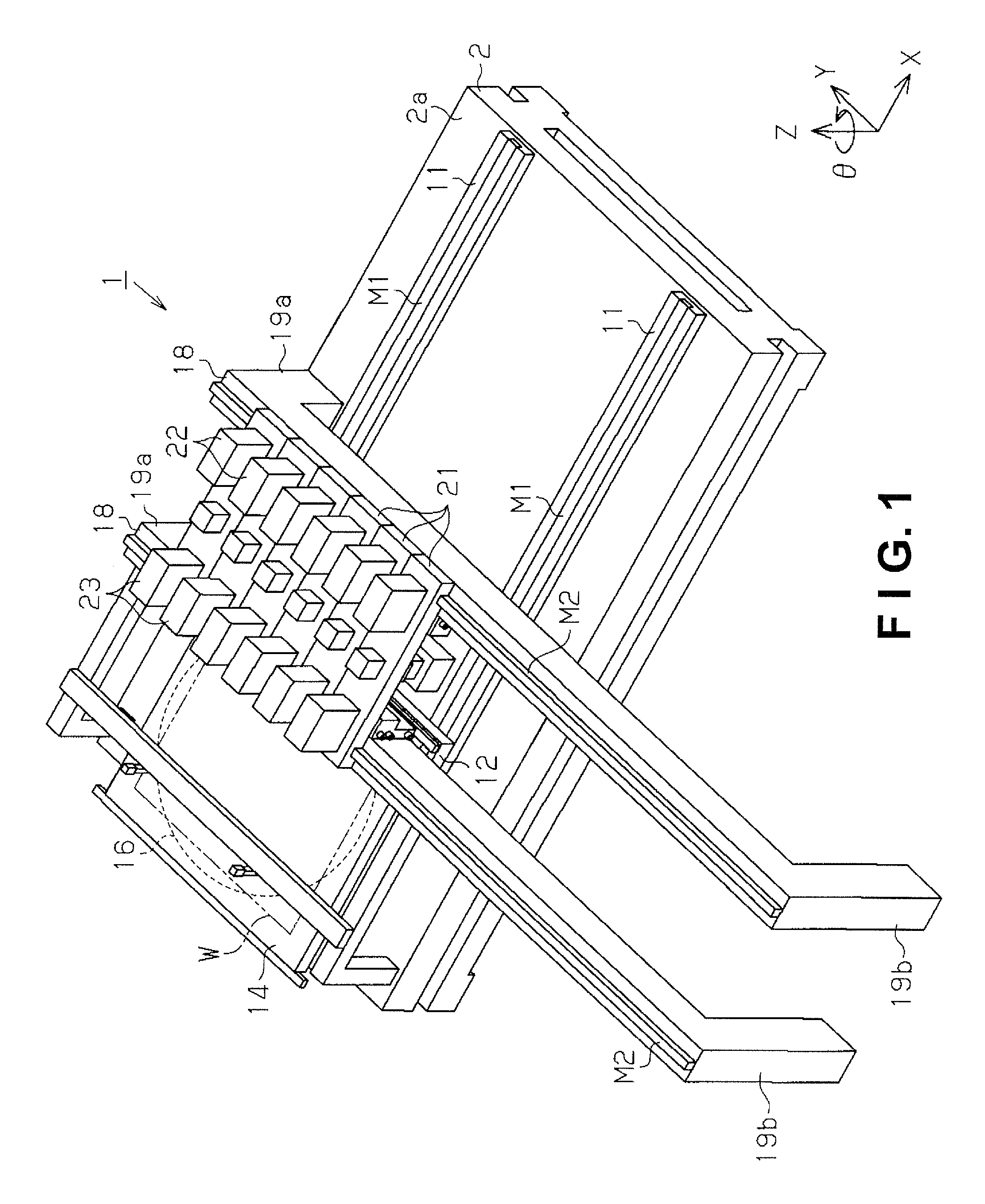
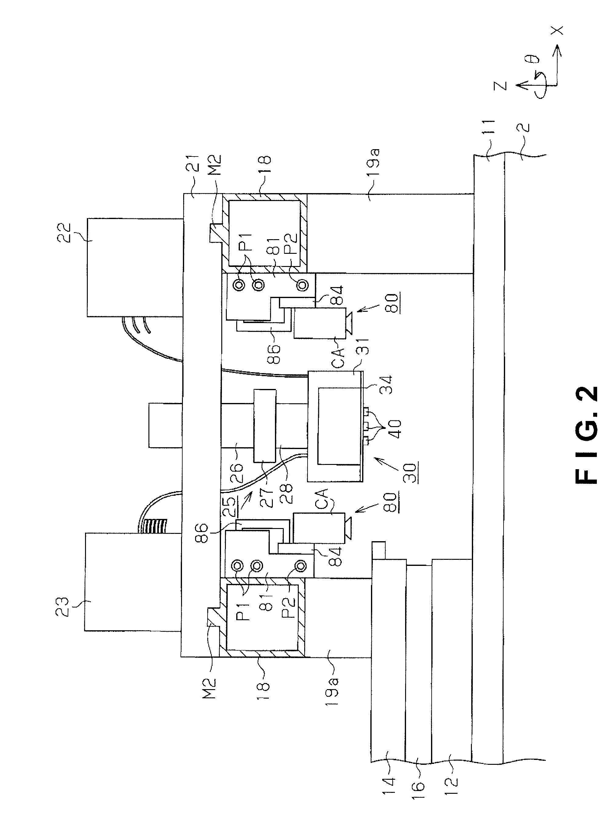
[0037]FIG. 1 shows the overall structure of the droplet discharge device 1 as the pattern formation device for forming red, green, and blue color filters on a glass substrate on which a black matrix is formed. In the droplet discharge device 1 as shown in FIG. 1, a base 2 that extends in the primary scanning direction (X-axis direction) is provided on a floor surface, a pair of X-axis guide rails 11 are laid on the upper surface 2a of the base in the primary scanning direction (X-axis direction), and an X-axis movement plate 12 is mounted on the pair of X-axis guide rails 11. The X-axis movement plate 12 is mounted so as to be able to move in the primary scanning direction along the X-axis guide rails 11. X-axis linear motors M1 are provided to the pair of X-axis guide rails 11, and the X-axis linear motors M1 move the X-axis movement pl...

second embodiment

[0073]A second embodiment of the present invention will be described below according to FIG. 6. For the sake of convenience in the present embodiment, aspects that differ from the first embodiment will be described in detail, and no detailed description will be given of aspects that are basically the same as in the first embodiment.

[0074]As shown in FIG. 6, through holes are formed in the Y-axis guide rail 18 and the base housing 81 of the drawing inspection camera device 80, and a plurality of communicating channels S for communicating the base housing 81 with the Y-axis guide rail 18 is provided by the through holes. Exhaust ports P3 are formed in the side walls of the Y-axis sides of the Y-axis guide rail 18. The exhaust ports P3 are connected to a suction pump (not shown). The suction pump is driven, and the air inside the Y-axis guide rail 18 is suctioned from the exhaust ports P3, whereby outside (near the carriage 30) air is drawn in from the drawer hole 85 of the cableveyor ...


PUM


Abstract

A pattern formation device includes a conveyance table, a pair of guide rails, a carriage, a plurality of droplet discharge heads, an inspection camera, a camera base, a linear motor, a motor housing case, a moving cable, and a cable housing case. The motor housing case is disposed along the guide rails to accommodate the linear motor and has a guide opening configured and arranged to guide the camera base. The cable housing case is disposed along the motor housing case to accommodate the moving cable and has a window section through which a distal end of the moving cable follows a reciprocal operation of the inspection camera. The cable housing case or one of the guide rails has an exhaust vent to discharge air around the carriage by suction through the window section of the cable housing case or the guide opening of the motor housing case.

Description

CROSS-REFERENCE TO RELATED APPLICATIONS[0001]This application claims priority to Japanese Patent Application No. 2007-255329 filed on Sep. 28, 2007. The entire disclosure of Japanese Patent Application No. 2007-255329 is hereby incorporated herein by reference.BACKGROUND[0002]1. Technical Field[0003]The present invention relates to a pattern formation device.[0004]2. Related Art[0005]An inkjet device, i.e., a droplet discharge device, for discharging a functional liquid in the form of droplets is commonly known as a pattern formation device for forming a desired pattern on a substrate using a functional liquid. The droplet discharge device forms a pattern by arranging droplets of a functional liquid discharged from a droplet discharge head in arbitrary locations on a substrate while moving the substrate mounted on a stage and the droplet discharge head for discharging droplets of the functional liquid relative to each other in two dimensions.[0006]A droplet discharge device has rece...

Claims


Application Information

Patent Timeline
Patent Type & Authority Patents(United States)
IPC IPC(8): B05C11/00
CPCB41J2/2142
Inventor FUJIMORI, EIJIRO
Owner TOKYO ELECTRON LTD
Why Eureka
Try Eureka