Vehicle-mounted multi-rotor unmanned aerial vehicle remote take-off and landing system

A multi-rotor UAV and unmanned aerial vehicle technology, applied in the direction of rotorcraft, control/regulation system, unmanned aircraft, etc., can solve the problems of reducing operation efficiency and safety, consuming large power, and low operation efficiency , to achieve the effect of improving operating efficiency and safety, accurate landing position, and reducing operating radius

Pending Publication Date: 2021-09-03
CHIZHOU POWER SUPPLY COMPANY STATE GRID ANHUI ELECTRIC POWER
View PDF3 Cites 0 Cited by
  • Summary
  • Abstract
  • Description
  • Claims
  • Application Information

AI Technical Summary

Problems solved by technology

In this mode of operation, the distance between the UAV returning to the take-off point will consume a lot of power, and the operation efficiency is low; (2) let the UAV take off from the starting point of the line, and automatically fly along the line to perform tasks. The human-machine operator needs to drive and hold the remote control to chase the aircraft, maintain communication with the drone, and control the drone to land after the drone reaches the end of the line or when the battery is low.
This traditional operation method requires manual operation of the take-off and landing of the drone, and the need to follow the drone throughout the process, which greatly reduces the efficiency and safety of the operation, and is prone to accidents
[0004] To sum up, due to the inconvenience caused by the traditional UAV operation method, it is necessary to design a reasonable UAV operation system to realize the take-off from the take-off point to the landing point, reduce the operating radius, improve the operation efficiency and safety, and realize the From takeoff to landing, high-precision identification and positioning are required to control the flight attitude of the UAV to land on the takeoff and landing platform or alternate landing point

Method used


Image

  • Vehicle-mounted multi-rotor unmanned aerial vehicle remote take-off and landing system
  • Vehicle-mounted multi-rotor unmanned aerial vehicle remote take-off and landing system
  • Vehicle-mounted multi-rotor unmanned aerial vehicle remote take-off and landing system

Examples


Embodiment Construction

[0030] The following will clearly and completely describe the technical solutions in the embodiments of the present invention with reference to the drawings in the embodiments of the present invention.

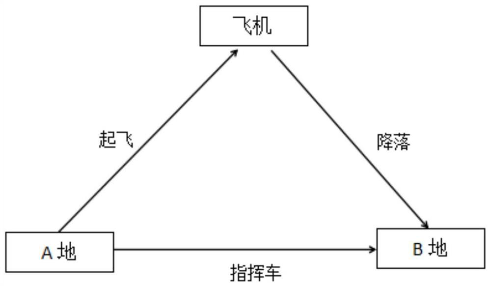
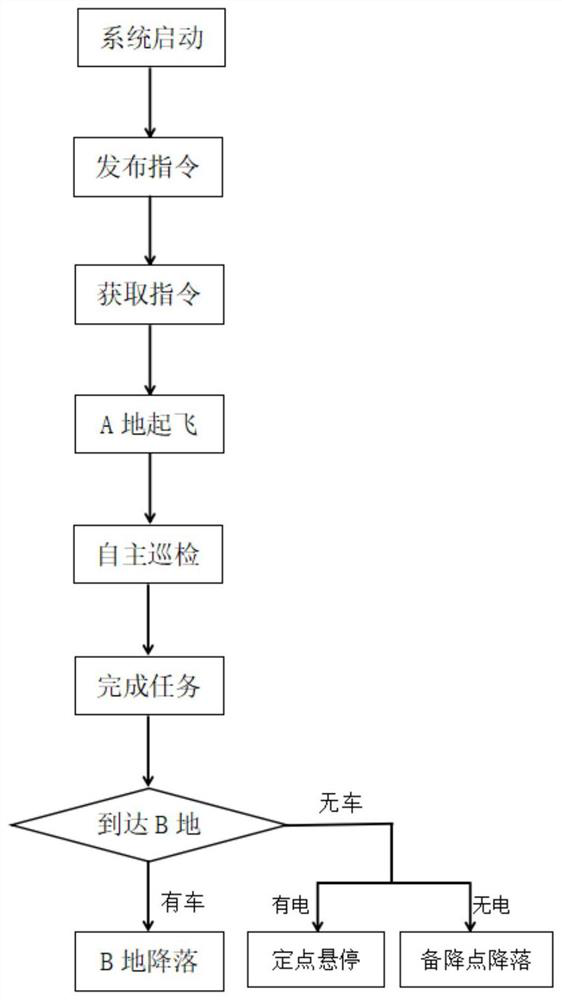
[0031] A vehicle-mounted multi-rotor unmanned aerial vehicle off-site take-off and landing system includes a multi-rotor unmanned aerial vehicle and a command vehicle. This system is suitable for blue-brand vehicles with a body less than 6m and a total mass of no more than 4500kg. It is also suitable for the take-off and landing or conversion of drones between one or more command vehicles; it can realize multi-rotor drones taking off from different places Landing, high-precision positioning and visual recognition enable the UAV to accurately land on the landing point or take-off and landing platform, so as to realize the take-off and landing at the take-off point, reduce the operating radius, and greatly improve the operating efficiency and safety.

[0032] In this embodiment,...


PUM


Abstract

The invention discloses a vehicle-mounted multi-rotor unmanned aerial vehicle remote take-off and landing system which comprises an unmanned aerial vehicle, a command vehicle and a landing preparation point preset at a landing place, the unmanned aerial vehicle is parked on a take-off place command vehicle take-off and landing platform, visual identification panels are arranged on the take-off and landing platform and the landing preparation point, and nested patterns are arranged on the visual identification panels; the unmanned aerial vehicle and the command vehicle are provided with positioning modules for accurate positioning of mutual positions and a wireless data transmission module for keeping mutual communication and data transmission, the unmanned aerial vehicle is further provided with a visual identification module for identifying nested patterns; the unmanned aerial vehicle arrives at the landing place before taking off, and lands after identifying the nested pattern of the take-off and landing platform or the standby landing point on the command vehicle. According to the invention, remote take-off and landing of the unmanned aerial vehicle can be realized, and the unmanned aerial vehicle can accurately land to a landing point through high-precision positioning, so that ground landing of a take-off landing ground is realized, the working radius is reduced, and the working efficiency and safety are greatly improved.

Description

Technical field: [0001] The invention relates to the research field of unmanned aerial vehicle power inspection, in particular to a vehicle-mounted multi-rotor unmanned aerial vehicle off-site take-off and landing system. Background technique: [0002] With the rapid development of my country's social economy and the rapid advancement of urbanization, more and more ultra-high voltage, large-capacity, and long-distance transmission lines are built, which are channels for electric energy transmission and an indispensable and important part of the power grid. The resources of the existing transmission corridors are becoming increasingly tight, and discharge accidents caused by transmission lines often occur. The traditional manual inspection is limited by natural conditions, and there are large errors and defects. This makes people realize that relying on the traditional regular inspection method to maintain the line operation can no longer guarantee the safe operation of the t...

Claims


Application Information

Patent Timeline
Patent Type & Authority Applications(China)
IPC IPC(8): G05D1/08G05D1/10B64F1/00B64C27/08B60P3/11
CPCG05D1/0808G05D1/101B64F1/00B64C27/08B60P3/11B64U10/10
Inventor 陈熙吴奎胡磊胡海琴严波操松元刘根宝郭可贵刘洋彭事奇胡锦超
Owner CHIZHOU POWER SUPPLY COMPANY STATE GRID ANHUI ELECTRIC POWER
Why Eureka
Try Eureka