Crossbow dry fire arrestor

a technology of dry fire arrestor and crossbow, which is applied in the field of crossbows, can solve the problems of increased firing velocity, damage or injury, damage to crossbow strings, cams and other components,

Inactive Publication Date: 2011-09-20
TOG IP LLC
View PDF4 Cites 35 Cited by
  • Summary
  • Abstract
  • Description
  • Claims
  • Application Information

AI Technical Summary

Benefits of technology

[0009]The present invention overcomes disadvantages of conventional systems by providing a self-contained dry fire arrestor that includes a dry fire member and a spring which holds the dry fire member in engagement with a trigger mechanism to prevent firing the crossbow unless an arrow or bolt is loaded in the crossbow.
[0010]The present invention provides an advantage of an automatic safety feature by immobilizing the crossbow trigger when an arrow or bolt is not properly loaded.
[0011]The present invention provides a further advantage of precluding any string travel absent proper loading of an arrow.
[0012]The present invention provides yet a further advantage of avoiding misfires and jamming.
[0013]The present invention is lightweight, reliable and can be incorporated into the trigger mechanism.

Problems solved by technology

However, increased firing velocity creates a problem of damage or injury when the crossbow is inadvertently fired when unloaded, i.e. when the crossbow is discharged without a bolt (also referred to as an arrow) that is loaded, i.e. pressed against the tensioned crossbow string.
Unloaded or dry firing impacts can damage the crossbow string, limbs, cams and other components.
Dry firing also creates a safety concern.
Further, the time required to reload a dry fired crossbow will often allow quarry to escape, which is a significant concern for crossbow hunters.
Conventional dry fire inhibitors fail to ensure proper loading of an arrow or bolt into the trigger mechanism and fail ensure that the arrow is properly nestled against the tensioned crossbow string.
Discharge when an arrow is not properly nestled against the tensioned string can result in the string becoming jammed beneath the incorrectly loaded arrow.
In addition, conventional dry fire inhibitors may ride along the arrow as the arrow is discharged, reducing crossbow accuracy.

Method used


Image

  • Crossbow dry fire arrestor
  • Crossbow dry fire arrestor
  • Crossbow dry fire arrestor

Examples


Embodiment Construction

[0032]The following detailed description of the preferred embodiment of the invention will be made in reference to the accompanying drawings. In describing the invention, explanation about related functions or constructions known in the art are omitted for the sake of clarity in understanding the concept of the invention, as such would obscure the invention with unnecessary detail.

[0033]As shown in FIGS. 13-16 crossbow 100 includes stock 110, barrel 120, dry fire arrestor 200, telescopic sight 150 and sight mount 140 which secures the sight on arrestor 200. The crossbow 100 has limbs 160 and string 170.

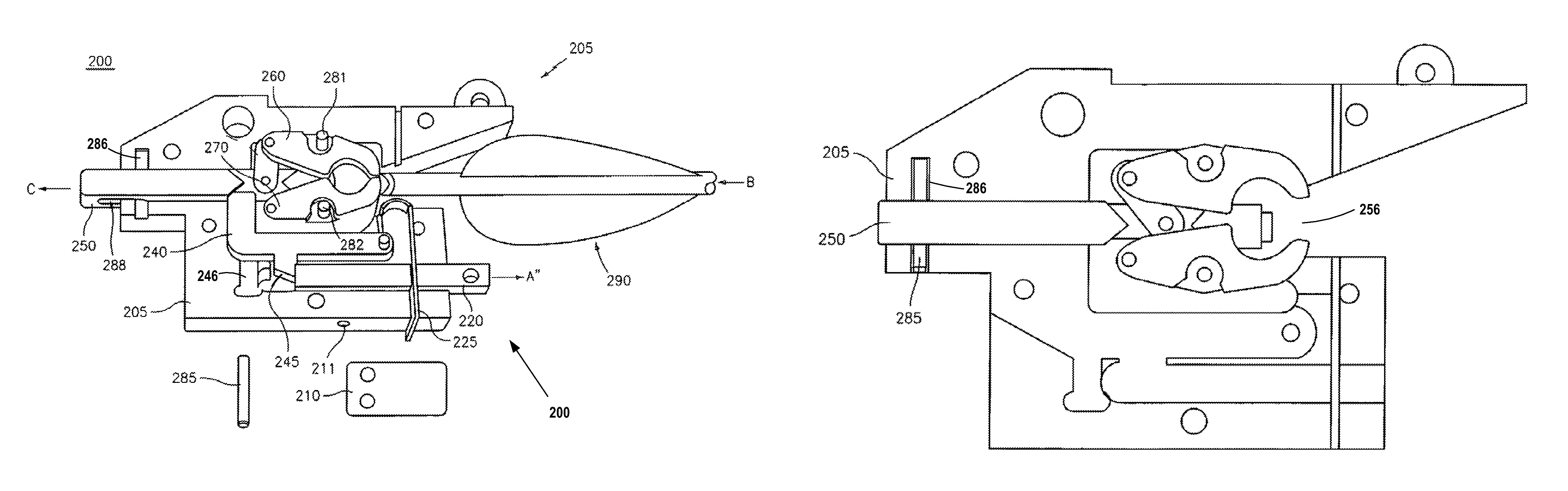
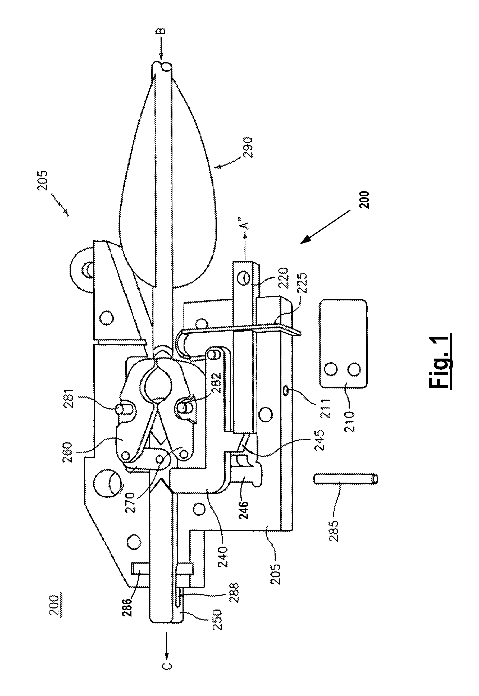
[0034]FIG. 1 provides a cutaway view of the crossbow dry fire arrestor 200 in an engagement, i.e. cocked position, with a tensioned crossbow string (not shown) held between closed upper and lower jaws 260, 270 awaiting firing of the crossbow. Upper and lower jaws 260, 270 are shown in an open position in FIG. 12 and are shown in a closed (or cocked) position in FIGS. 1, 6 and 8.

[0035]...


PUM


Abstract

Disclosed in a dry fire arrestor for a crossbow having a trigger mechanism operable to fire an arrow or bolt, that includes a spring plate, trigger sear connected to the trigger mechanism, an anti-dry fire bar for engaging and disengaging the trigger sear. The dry fire arrestor utilizes tension provided by the spring plate to allows anti dry fire bar to automatically engage the trigger sear, precluding movement of the trigger when an arrow in not properly inserted in the dry fire arrestor.

Description

[0001]This application claims priority to provisional application Ser. No. 60 / 881,076, filed with the U.S. Patent and Trademark Office on Jan. 18, 2007, the contents of which are incorporated herein by reference.BACKGROUND OF THE INVENTION[0002]1. Field of Invention[0003]The present invention relates generally to crossbows, and in particular to trigger mechanisms for preventing firing of a crossbow without a bolt loaded therein.[0004]2. Description of the Related Art[0005]Crossbows have been used since the Middle Ages. Crossbows have evolved to include cams and synthetic split limbs that greatly increase firing velocity. However, increased firing velocity creates a problem of damage or injury when the crossbow is inadvertently fired when unloaded, i.e. when the crossbow is discharged without a bolt (also referred to as an arrow) that is loaded, i.e. pressed against the tensioned crossbow string. Unloaded or dry firing impacts can damage the crossbow string, limbs, cams and other com...

Claims


Application Information

Patent Timeline
Patent Type & Authority Patents(United States)
IPC IPC(8): F41B5/12
CPCF41B5/12F41B5/1469
Inventor MALESKI, RICHARDWILBER, CARLMIECZKOWSKI, KENNETH
Owner TOG IP LLC
Why Eureka
Try Eureka