Windrower tractor with rear wheel suspension

a rear wheel suspension and tractor technology, applied in the direction of resilient suspensions, steering wheels, vehicle springs, etc., can solve the problems of increasing power requirements, increasing fuel consumption, and shimmy of the castor, so as to reduce the shock load of the walking beam, reduce the impact load, and reduce the effect of articulation

Inactive Publication Date: 2011-09-20
MACDON INDS
View PDF7 Cites 60 Cited by
  • Summary
  • Abstract
  • Description
  • Claims
  • Application Information

AI Technical Summary

Benefits of technology

[0032]Preferably each of the first pair of ground wheels is driven by a respective drive motor which allows variable speed in both the first and second directions such that steering of the tractor is effected by a differential in speed between the first wheels with the second wheels following the steering in a castoring action.
[0037]The torsion arm suspension system described herein is simple with few moving parts. The two rear caster wheels can move independently of each other while remaining connected through a solid beam rigidly connected to the main frame of the tractor. This arrangement provides greater articulation and requires less strength than an arrangement using a pivotal rear axle, particularly at the area where the beam pivots at the frame. The arrangement also provides a reduced shock loading of walking beam and caster components. The suspension can react faster due to less mass of the suspension components. The suspension provides dampening in some cases without the need for hydraulic shock absorbers. The rubber will inherently help to dampen the suspension but additional dampening, like a shock absorber, may be provided.

Problems solved by technology

Castor shimmy is an inherent problem on tractors of the above type.
Loss of ground contact (going over bumps) also aggravates the problem and as a result weight is often added to prevent this.
This results in increased power requirements and increased fuel consumption.
However the use of only the tires as a suspension in rough terrain can cause sever pitching leading to significant fore and aft acceleration of the operator station.
This arrangement has obtained some acceptability but is relatively complex.

Method used


Image

  • Windrower tractor with rear wheel suspension
  • Windrower tractor with rear wheel suspension
  • Windrower tractor with rear wheel suspension

Examples


Embodiment Construction

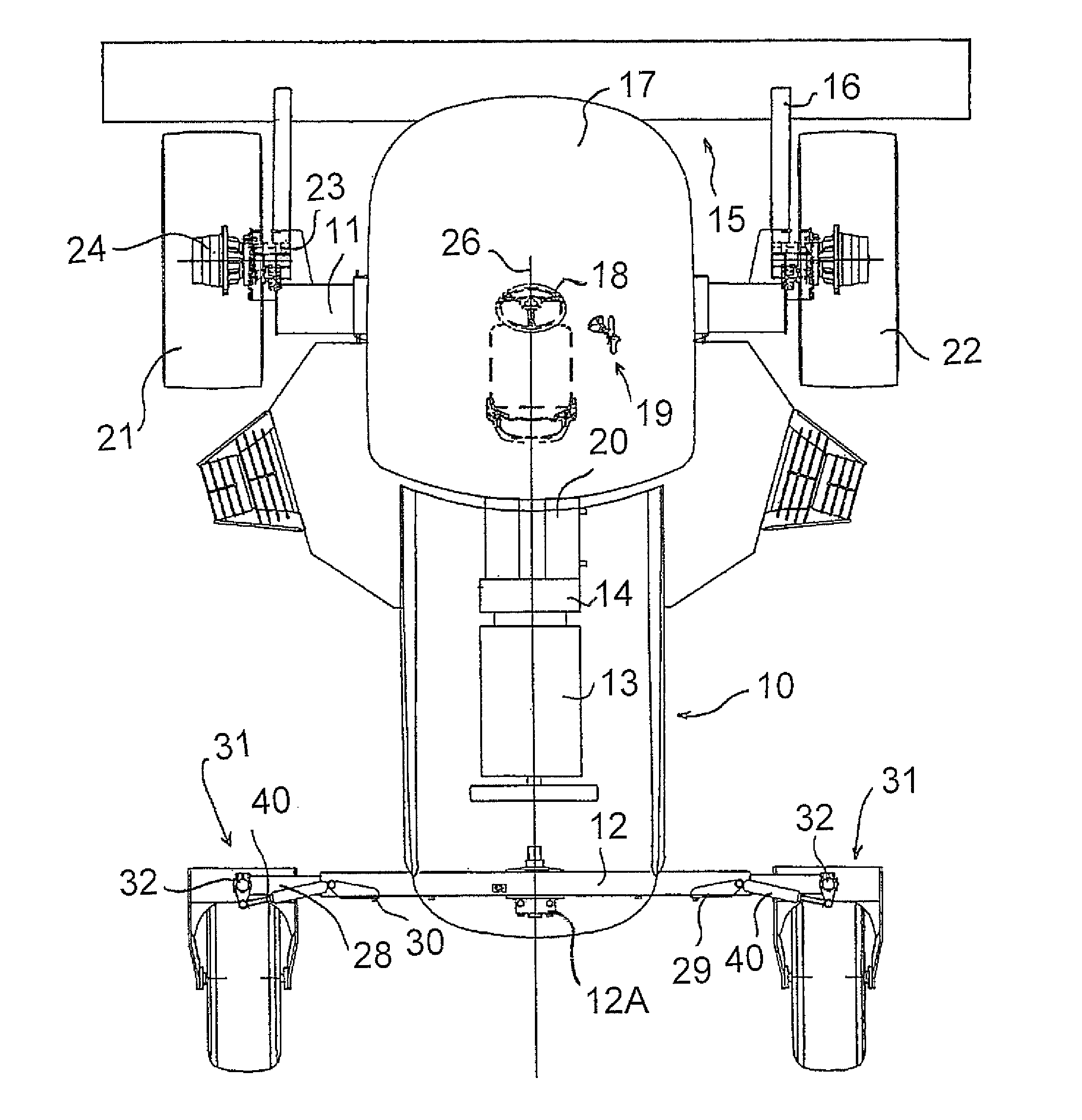
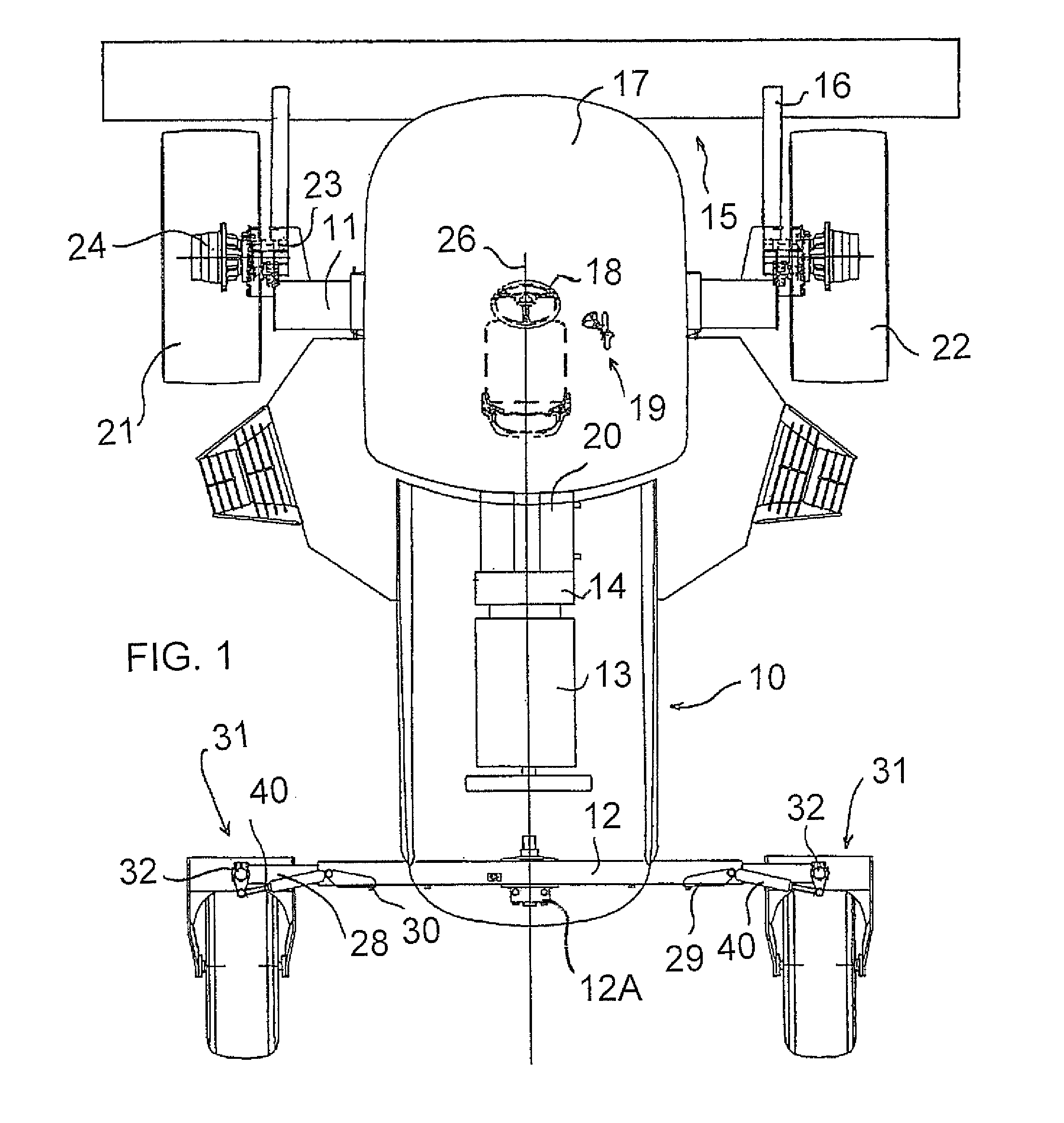
[0047]In FIG. 1 is shown a tractor of the above type which includes a frame 10 with a front axle 11 and a rear axle 12. On the frame 10 is mounted a motor 13 driving a gear box and pump assembly schematically indicated at 14 for communicating hydraulic drive fluid to the various components of the tractor for propelling the tractor and for driving an implement 15 mounted on the tractor. In one example, the engine drives a gearbox at the rear of the engine that splits the power to two pump assemblies. One pump assembly has two pumps (one for each wheel) for traction drive & each pump controls one wheel. The other pump assembly has four pumps (two for header drive, one for lift functions and one providing supercharge oil). In the embodiment shown the implement is a header arranged for cutting a standing crop with the header carried on support arms 16 mounted on the tractor at the forward end in conventional manner. The tractor includes a cab 17 including steering 18 and control element...


PUM


Abstract

A tractor has front wheels mounted on the frame at fixed angles and a pair of rear wheels each mounted on a respective castor assembly. Each of the castor assemblies has a vertical pivot axis mounted in a swivel support of an axle of the frame and a bottom transverse tubular member connected to a pair of parallel forks carrying at a lower ends the transverse axle of the wheel. The mounting link includes a torsion spring defined by a rod attached to the forks which passes though a sleeve containing a resilient elastomeric spring of the tubular member allowing spring suspension pivotal movement of the upper ends of the forks relative to the bottom transverse member about an axis parallel to the wheel axis.

Description

[0001]This application claims the benefit under 35 U.S.C. 119 of the filing date of Provisional Application 61 / 159,592 filed Mar. 12, 2009.[0002]This invention relates to a swather or windrower tractor with rear wheel suspension.BACKGROUND OF THE INVENTION[0003]In U.S. Pat. No. 7,077,220 (Dunn) issued Jul. 18, 2006 and assigned to the present Assignees is disclosed a hydrostatic agricultural tractor used as a self propelled swather tractor. This uses the typical construction for such tractors which has front ground wheels mounted on the frame at fixed angles parallel to each other and parallel to a center line of the frame and rear ground wheels mounted on a respective castor. Each of the front ground wheels is driven by a respective drive motor which allows variable speed in both the first and second directions such that steering of the tractor is effected by a differential in speed between the front wheels with the rear wheels following the steering in a castoring action. A pair o...

Claims


Application Information

Patent Timeline
Patent Type & Authority Patents(United States)
IPC IPC(8): B62D11/02
CPCB60B33/045B60G5/025B60G11/225B60G11/24B60G99/004F16F1/545B60G2200/32B60G2200/42B60G2200/44B60G2202/1424B60G2204/125B60G2204/143B60G2204/18B60G2204/423B60G2204/4302B60G2300/082B60G2300/40
Inventor OTTO, PHILIP J.
Owner MACDON INDS
Why Eureka
Try Eureka