Impact load reduction structure

a technology of impact load and structure, which is applied in the direction of bumpers, vehicle sub-unit features, electric devices, etc., can solve the problems of large impact load input to the batteries of electrically-powered vehicles, large capacity and weight of batteries installed in electric vehicles and hybrid vehicles, and large impact load

Active Publication Date: 2017-03-30
SUBARU CORP
View PDF39 Cites 27 Cited by
  • Summary
  • Abstract
  • Description
  • Claims
  • Application Information

AI Technical Summary

Benefits of technology

[0008]It is desirable to provide an impact load reduction structu

Problems solved by technology

Batteries installed in electrically-powered vehicles, such as electric vehicles and hybrid vehicles, require large capacity and have large weight.
Thus, when the front section of the electri

Method used


Image

  • Impact load reduction structure
  • Impact load reduction structure
  • Impact load reduction structure

Examples


first example

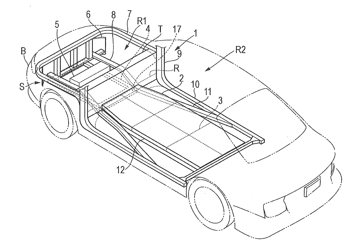
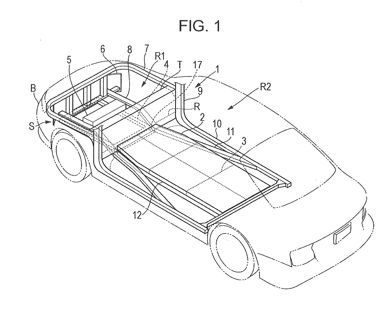
[0021]FIG. 1 illustrates the configuration of an electric vehicle equipped with an impact load reduction structure according to a first example of the present invention. This electric vehicle has a vehicle body frame 1 that supports a vehicle body, a battery housing 2 fixed to the vehicle body frame 1, a plurality of batteries 3 disposed within the battery housing 2, a sub frame 4 disposed on the front side of the battery housing 2, and a driving unit 5 electrically coupled to the plurality of batteries 3 via wires (not illustrated).

[0022]The vehicle body frame 1 has a bumper frame 6, a pair of front upper frames 7, a pair of front side frames 8, a pair of front pillars 9, a pair of side sills 10, and a pair of floor side frames 11.

[0023]The bumper frame 6 is disposed at the front section of the electric vehicle and supports a bumper B. The bumper frame 6 extends in a curved manner in the vehicle width direction. The bumper frame 6 and the bumper B have a crash area S that deforms f...

second example

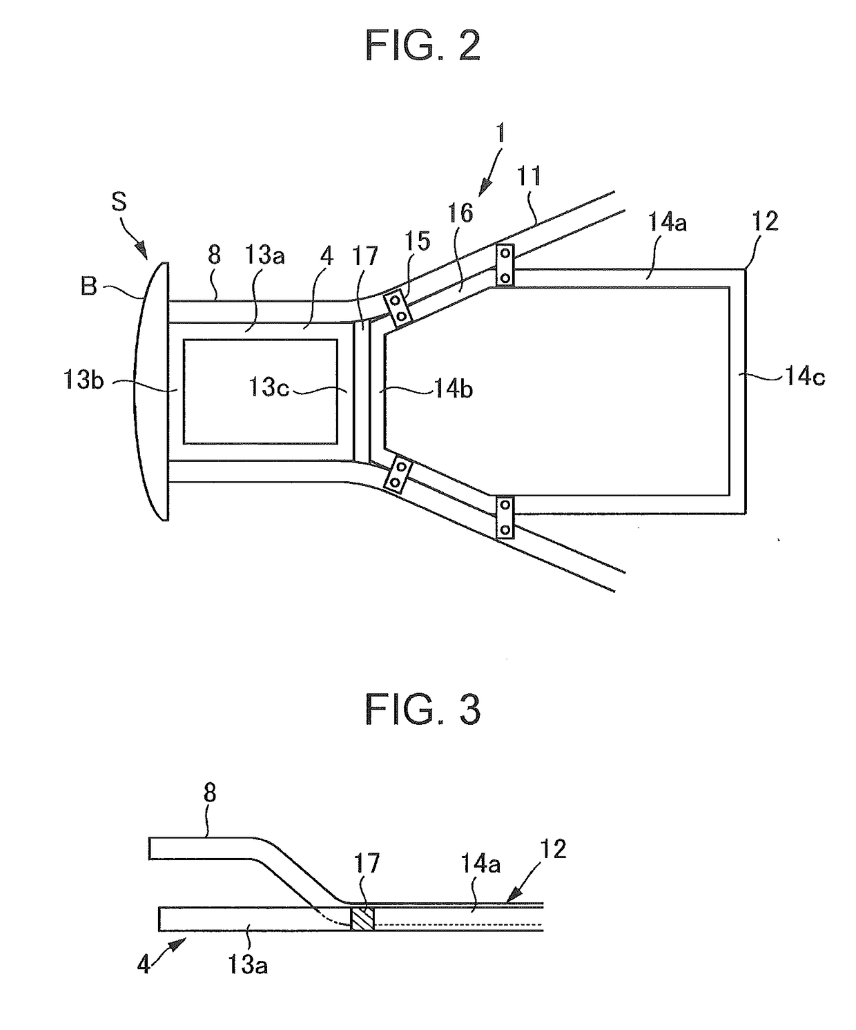
[0052]In the first example, the load absorber 17 has lower rigidity than the battery frame 12 and higher rigidity than the sub frame 4. Alternatively, the sub frame 4 may have lower rigidity than the battery frame 12, and the load absorber 17 may have lower rigidity than the sub frame 4.

[0053]Similar to the first example, when the front section of the electric vehicle illustrated in FIG. 1 collides with the impactor D, the crash area S of the bumper B deforms in a crushed manner. Moreover, the impact load input from the bumper B is transmitted rearward via the front upper frames 7, the front side frames 8, and the sub frame 4.

[0054]In this case, since the load absorber 17 has lower rigidity than the sub frame 4, transmission of the impact load from the sub frame 4 to the battery frame 12 is reduced, so that the battery frame 12 receives only a portion of the impact load transmitted through the floor side frames 11. Therefore, in the early stage of the collision, the battery frame 12...


PUM


Abstract

An impact load reduction structure includes a battery frame, a load reduction frame, and a load absorber. The battery frame is fixed to a vehicle body frame of an electrically-powered vehicle and supports a battery. The load reduction frame extends in a front-rear direction on a front side of the battery frame and is disposed in a substantially same plane as the battery frame. The load absorber is disposed between the load reduction frame and the battery frame and absorbs an impact load to be transmitted from the load reduction frame to the battery frame.

Description

CROSS-REFERENCE TO RELATED APPLICATIONS[0001]The present application claims priority from Japanese Patent Application No. 2015-193462 filed on Sep. 30, 2015, the entire contents of which are hereby incorporated by reference.BACKGROUND[0002]1. Technical Field[0003]The present invention relates to impact load reduction structures, and particularly, to an impact load reduction structure that reduces an impact load transmitted to a battery for driving an electrically-powered vehicle.[0004]2. Related Art[0005]Batteries installed in electrically-powered vehicles, such as electric vehicles and hybrid vehicles, require large capacity and have large weight. Therefore, an electrically-powered vehicle is normally provided with a battery frame for supporting a battery. For instance, the battery frame is provided in a large space under the floor of the vehicle cabin, and a plurality of batteries are collectively disposed within the battery frame. There is a demand for a technology for suppressin...

Claims


Application Information

Patent Timeline
IPC IPC(8): B62D21/15B62D25/02B60L11/18B60K1/04
CPCB62D21/15B60L11/1879B62D25/025B60K1/04B60R19/18B60K2001/0438B60L3/0007B60L50/64B60L50/66B60Y2306/01B62D21/155B62D25/082B62D25/2018Y02T10/70
Inventor TSUKADA, TAKEHISAMATSUDA, HIROSHI
Owner SUBARU CORP
Why Eureka
Try Eureka