Lifting mechanism braking system of hoister

A technology of lifting mechanism and braking system, which is applied in the direction of clockwork mechanism, load suspension components, hoisting device, etc., which can solve the problems of accelerated descent, equipment and staff injury, equipment damage, etc., and reduce the impact load, avoid damage to parts, and ensure safety

Inactive Publication Date: 2005-08-17
TAIYUAN HEAVY IND
View PDF0 Cites 28 Cited by
  • Summary
  • Abstract
  • Description
  • Claims
  • Application Information

AI Technical Summary

Problems solved by technology

Under normal circumstances, only the working brake and the auxiliary brake are put into operation. When the detection system detects a failure in a link in the mechanical transmission chain composed of the motor, coupling and reducer, such as overspeed, broken shaft or coupling failure, for The first type of braking system, because there is only a brake on the high-speed shaft, and no safety brake is installed on the low-speed shaft, that is, the drum flange, the hoisted object will accelerate and descend with a large acceleration under the action of gravity. Possible damage to equipment and personal injury
For the second type of braking system, since there is no sequence requirement for the application of the working brake, the auxiliary brake and the safety brake, the safety brake will be applied before the working brake and the auxiliary brake. A large braking torque makes the low-speed shaft stop rotating in a short time, and the energy of the large moment of inertia of the motor, brake wheel (disk) on the high-speed shaft will also be consumed in a short time , thus causing a large impact load to the mechanical transmission chain composed of the motor, coupling and reducer, and the impact load often causes damage to a certain part of the transmission chain, and often causes major accidents of equipment and staff injuries

Method used


Image

  • Lifting mechanism braking system of hoister
  • Lifting mechanism braking system of hoister
  • Lifting mechanism braking system of hoister

Examples


Embodiment Construction

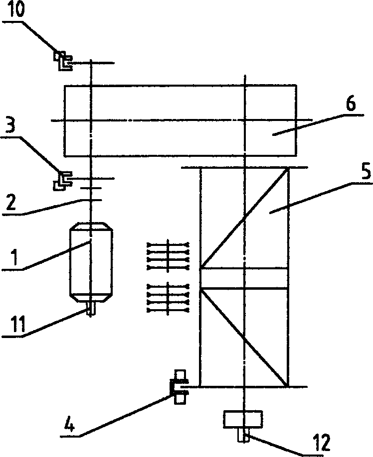
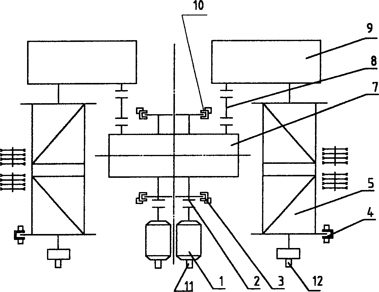
[0020] figure 1 Shown is the braking system of the hoisting mechanism of the single drum of the crane; the mechanical transmission chain of the hoisting mechanism of the crane is composed of the motor 1, the coupling 2, the reducer 6 and the drum 5. figure 2 As shown, the braking system of the double-drum hoisting mechanism consists of a motor 1, a coupling 2, a central reducer 7, a coupling 8 with a floating shaft, a secondary reducer 9 and a drum 5 to form a crane hoisting mechanism mechanical transmission chain. The braking system of the hoisting mechanism includes: the mechanical transmission chain of the hoisting mechanism; a pulse encoder is installed at the shaft end of the motor on the mechanical transmission chain, a pulse encoder is installed at the shaft end of the reel, and an overspeed switch for detecting the motor speed, etc. A fault detection element 11; a working brake 3 is installed on the high-speed shaft of the reducer in the mechanical transmission chain...


PUM


Abstract

The hoist mechanism braking system for crane includes mainly a work brake on the high speed shaft of the speed reducer in the mechanical transmission chain, a hydraulic safety brake installed on the winding drum flange, and an electric control system comprising industrial control computer or programmable controller and control circuit. Normally, the safety brake is always in power-on state after the crane is powered on and is turned off in case of failed power supply system of the crane or failed hoist mechanism. The present invention features that in case that the hoist mechanism fails, the detection element detected signal will be fed to the control system and the control system outputs some signal to control the work brake to shut off first and the safety brake to shut off after some time delay. Or, in emergency, the throttle valve in the safety brake is utilized to make the safety brake to lag shut off. The present invention reduces the impact load of shut safety brake on the mechanical transmission chain, decreases the damage of parts and ensures safety.

Description

technical field [0001] The invention belongs to hoisting and transporting machinery, and in particular relates to a braking system and a control method of a hoisting mechanism of a crane. Background technique [0002] At present, there are generally two types of brake systems for crane hoisting mechanisms. One is to install a working brake on the high-speed shaft, or a working brake and an auxiliary brake. The second type is that in addition to the working brake and auxiliary brake on the high-speed shaft, a safety brake is also installed on the flange at the end of the reel. Under normal circumstances, only the working brake and the auxiliary brake are put into operation. When the detection system detects a failure in a link in the mechanical transmission chain composed of the motor, coupling and reducer, such as overspeed, broken shaft or coupling failure, for The first type of braking system, because there is only a brake on the high-speed shaft, and no safety brake is i...

Claims


Application Information

Patent Timeline
Patent Type & Authority Applications(China)
IPC IPC(8): B66C15/00B66D5/02B66D5/24
CPCB66D1/14B66D1/12
Inventor 王首成顾翠云刘大淮安剑
Owner TAIYUAN HEAVY IND
Why Eureka
Try Eureka