Mast Lift and Mast Lift System

a technology which is applied in the field of mast lift and mast lift system, can solve the problems of cumbersome and difficult maneuverability of existing ladders, limited work area of users, and difficulty in adjusting the height of the mast lift, so as to reduce the peak impact load

Active Publication Date: 2008-12-25
JLG IND INC
View PDF54 Cites 27 Cited by
  • Summary
  • Abstract
  • Description
  • Claims
  • Application Information

AI Technical Summary

Benefits of technology

[0010]An energy absorbing feature may be provided between the platform and the carriage that reduces the peak impact load that can be exerted on the structure. This feature provides a type of elastic bumper and / or crumple zone in the unlikely event of complete hoist rope failure and emergency brake deployment.

Problems solved by technology

Existing ladders, however, can be cumbersome and difficult to maneuver.
Additionally, conventional ladders can be unstable particularly on uneven ground, and a work area is limited to the user's reach.
Ladder companies are reluctant to develop powered mechanical products.
However, existing mast climbers have minimum SWL loads of 1000 lbs and are not portable or operable by a single user due to their size.
These machines are also typically too large for portability and are very far from the many advantages provided by a ladder in terms of portability, low cost and ease of use.

Method used


Image

  • Mast Lift and Mast Lift System
  • Mast Lift and Mast Lift System
  • Mast Lift and Mast Lift System

Examples


Embodiment Construction

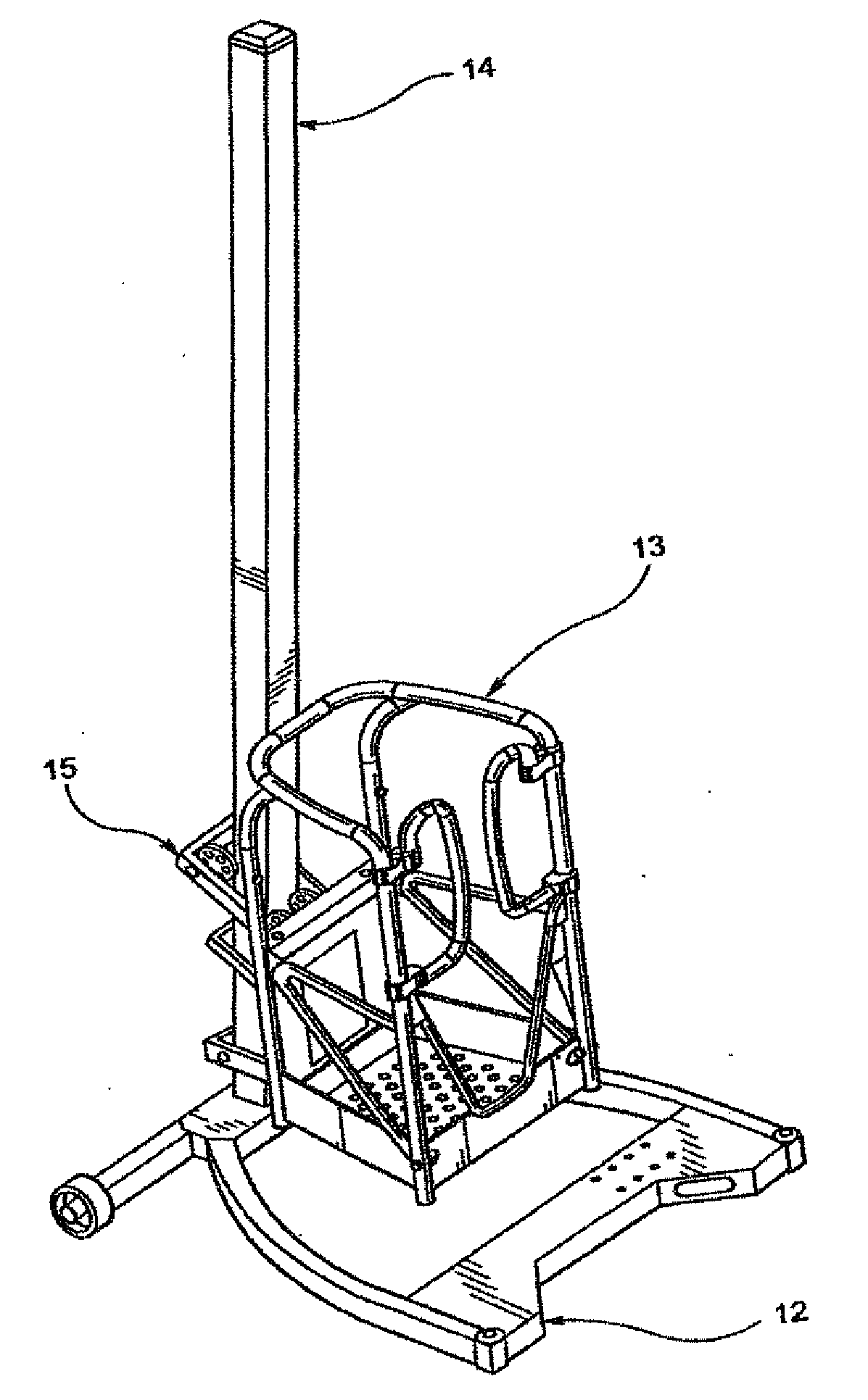
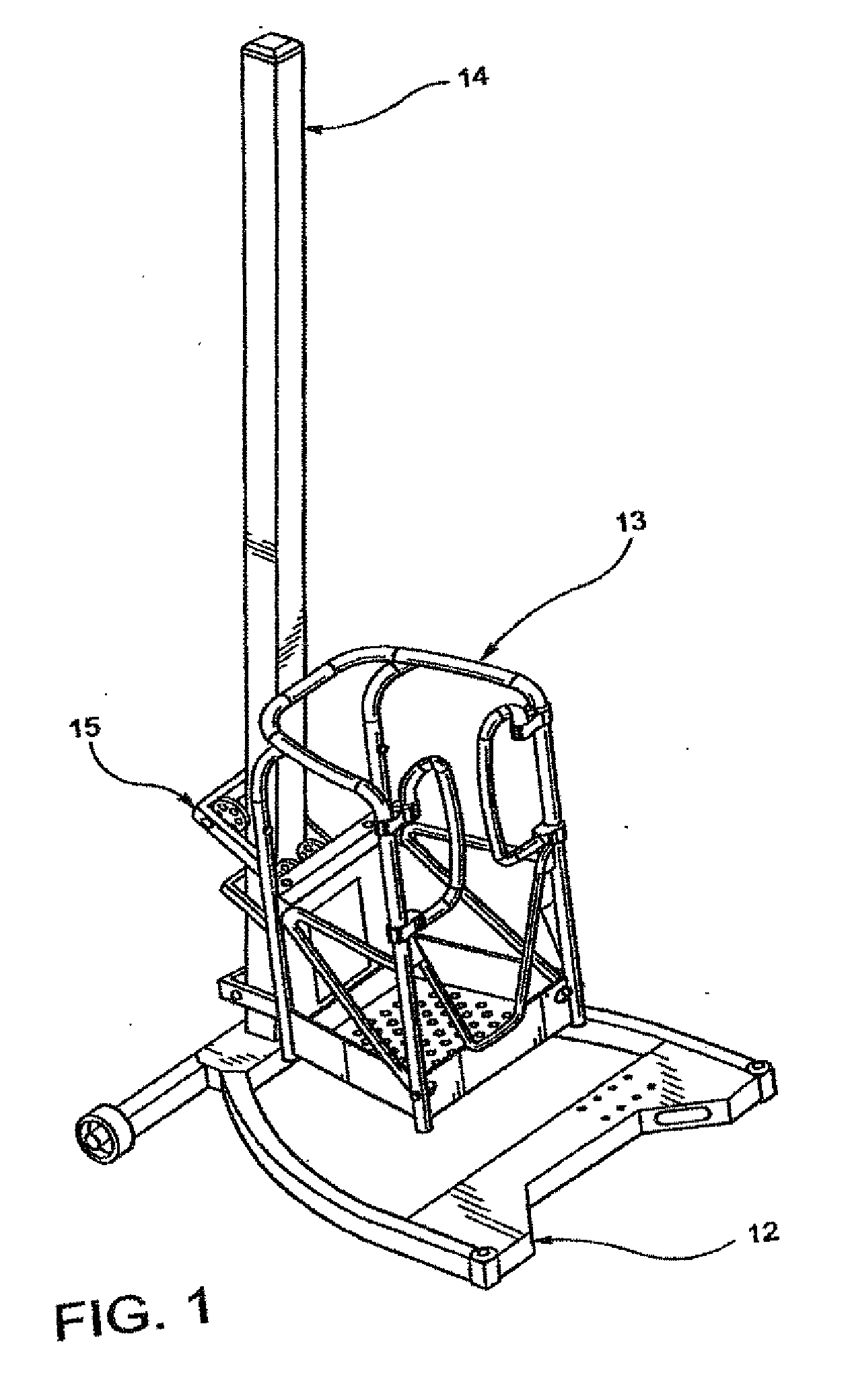
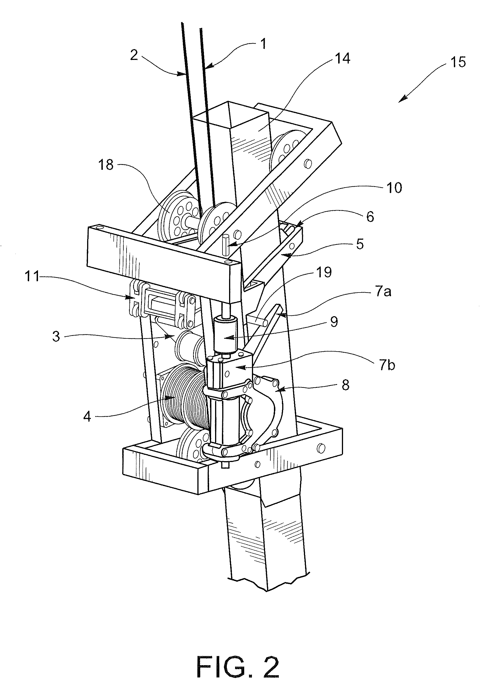
[0025]With reference to FIG. 1, the mast lift described herein generally includes a base or mast frame 12 supporting a mast 14 on which a work platform 13 is movable between a lowered position (shown in FIG. 1) and a raised position via a carriage assembly or lift system 15. Preferably, the components are modular, thereby enabling the machine to be quickly and reliably assembled and disassembled for ease of transport by one person. Component assembly typically takes the average skilled worker less than 30 seconds. The modular system also allows various components to be used on different types of mast and base designs, increasing product versatility. In an alternative embodiment, the mast 14 includes telescoped sections to provide for a greater height mast that can retract to be more compact for transport. The mast lift shown in FIG. 1 is a free-standing mast lift, i.e., the machine is capable of independent support and positioning. The components of the lifting structure described b...


PUM


Abstract

A lift system is coupled between a work platform and a mast on a mast lift. The lift system includes at least one lifting rope connected between the work platform and the mast via an idler roller and a hoist drum connected to the work platform. The idler roller is displaceable between an engaged position and a disengaged position based on an amount of tension on the lifting rope. A spring is connected to the idler roller and urges the idler roller toward the engaged position. A carriage latch assembly includes a carriage latch hook coupled with the idler roller and a pin secured to the mast. When the idler roller is disposed in the engaged position, the carriage latch hook is engageable with the pin.

Description

CROSS-REFERENCES TO RELATED APPLICATIONS[0001]This application is a continuation-in-part of PCT International Patent Application No. PCT / US2007 / 007060 filed Mar. 22, 2007 which claims the benefit of U.S. Provisional Patent Application Ser. No. 60 / 784,473, filed Mar. 22, 2006, the entire content of each of which is herein incorporated by reference.STATEMENT REGARDING FEDERALLY SPONSORED RESEARCH OR DEVELOPMENT[0002](Not Applicable)BACKGROUND OF THE INVENTION[0003]The present invention relates to a personnel lift and, more particularly, to a portable lift machine including a work platform raised and lowered on a mast by a lifting system. The lifting machine may be free-standing or non free-standing, transportable and operable by a single user.[0004]The ladder concept is several thousand years old. Existing ladders, however, can be cumbersome and difficult to maneuver. Additionally, conventional ladders can be unstable particularly on uneven ground, and a work area is limited to the us...

Claims


Application Information

Patent Timeline
Patent Type & Authority Applications(United States)
IPC IPC(8): B66F9/08
CPCB66F11/04B66F17/006
Inventor CAMPBELL, GEOFFREY GEORGESTARK, HUGH LITHGOWMCNEIL, ALEXANDER MCKECHRAN HARDIEFORNASARI, FRANK
Owner JLG IND INC
Why Eureka
Try Eureka