Magnetic friction clutch

a magnetic friction clutch and clutch technology, applied in the field of magnetic friction clutches, can solve the problems of high probability of damage to components in the drive, disadvantages, and relatively high manufacturing cost of toothed clutches, and achieves good magnetic permeability, high torque transfer, and increased disc friction coefficient

Inactive Publication Date: 2011-09-20
MAGNA CLOSURES INC
View PDF14 Cites 9 Cited by
  • Summary
  • Abstract
  • Description
  • Claims
  • Application Information

AI Technical Summary

Benefits of technology

[0012]The present invention provides a novel magnetic friction clutch which is capable of relatively high torque transfer for friction discs of a given diameter, compared to prior art magnetic clutches. A friction coating with a good magnetic permeability, such as Ferrous Aluminide or the like, is applied to inner and outer annular regions of the three friction discs and increases the frictional coefficient of the discs with little reduction in the clamping force developed through the clutch.

Problems solved by technology

While such toothed clutches have been widely used, they do suffer from disadvantages.
Further, in the event of an overload condition occurring in a drive system including a toothed clutch, there is a high probability that damage will occur to components in the drive system as the clutch cannot slip and thus the drive components must transfer the overload forces.
Also, toothed clutches are relatively expensive to manufacture.
While prior art magnetic friction clutches are used in a variety of applications and offer advantages over toothed clutches, they also suffer from disadvantages when the space into which the clutch is to be installed is limited and / or the torque that the clutch must transfer is relatively high.
In particular, known magnetic friction clutches have not been suitable for vehicular applications, such as liftgate openers, which require a relatively high torque transfer capability and yet have limited volume in which the clutch can be installed.

Method used


Image

  • Magnetic friction clutch
  • Magnetic friction clutch
  • Magnetic friction clutch

Examples


Embodiment Construction

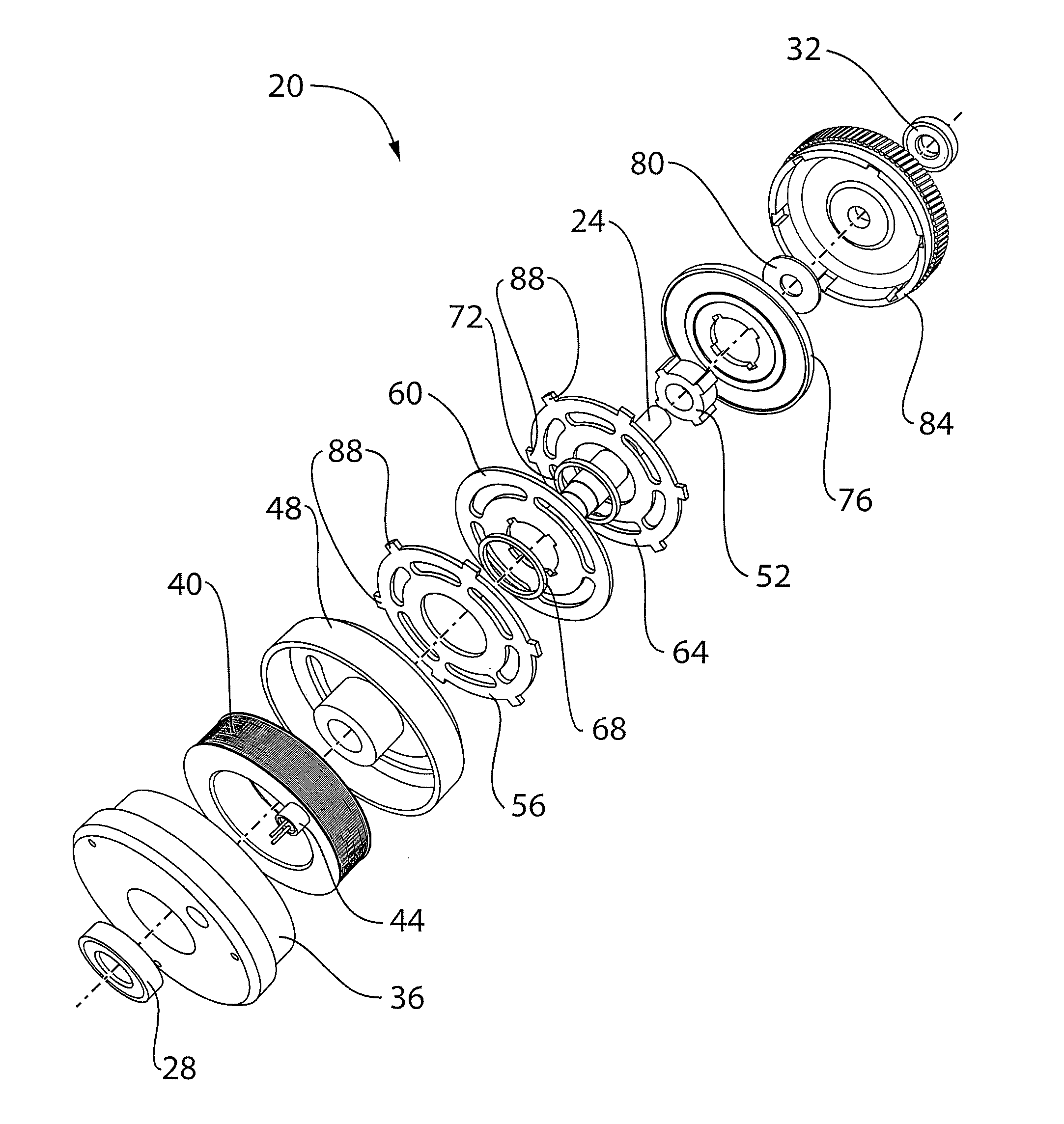
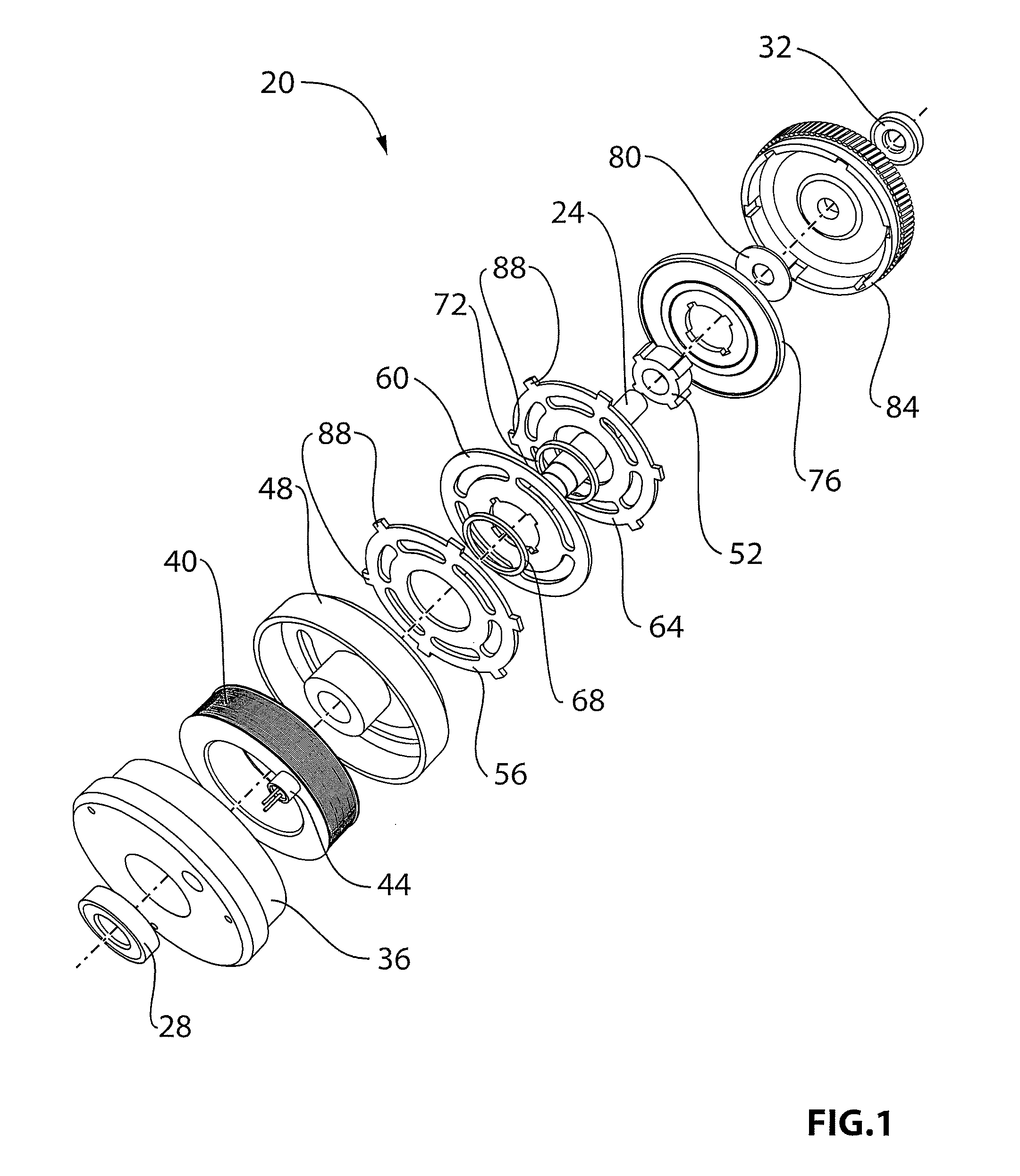
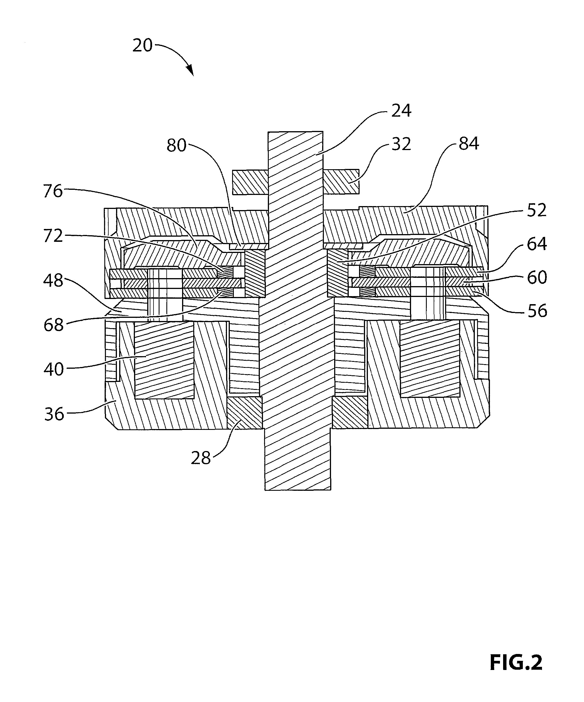
[0018]An embodiment of a magnetic friction clutch, in accordance with the present invention, is indicated generally at 20 in FIGS. 1 and 2. Clutch 20 includes an output shaft 24 which rotates on a pair of bearings 28 and 32. Output shaft 24 is connectable to a device to be driven, such as a vehicle liftgate or other device that requires torque from a prime mover, delivered via clutch 20.

[0019]In the embodiment illustrated in FIGS. 1 and 2, it is contemplated that the device to be driven will connect to the end of output shaft 24 adjacent bearing 28, but it is also contemplated that, in other embodiments, the device to be driven can be connected to the end of output shaft 24 adjacent bearing 32.

[0020]Clutch 20 further includes a magnetic core 36 which holds an electromagnetic winding 40. Magnetic core 36 is preferably manufactured from a material, such as iron, with good magnetic permeability which promotes the creation and forming of magnetic fields.

[0021]Electromagnetic winding 40 ...


PUM


Abstract

A novel magnetic friction clutch is disclosed which is capable of relatively high torque transfer for friction discs of a given diameter, compared to prior art magnetic clutches. A friction coating with good magnetic permeability, such as Ferrous Aluminide or the like, is applied to inner and outer annular regions of the three friction discs and increases the frictional coefficient of the discs with little reduction in the clamping force developed through the clutch.

Description

FIELD OF THE INVENTION[0001]The present invention relates to a clutch mechanism for drive systems such vehicle door or liftgate opening mechanisms. More particularly, the present invention relates to a magnetic friction clutch for such drive systems and other suitable applications.BACKGROUND OF THE INVENTION[0002]Many drive systems, such as vehicle liftgate openers, include a clutch which operates to disengage the electric drive from the mechanism which normally operates the liftgate so that manual operation of the liftgate can be achieved. Conventionally, such clutches have been mechanical toothed clutches which provide the necessary torque handling capabilities required for drive systems for operating heavy devices such as vehicle liftgate openers.[0003]While such toothed clutches have been widely used, they do suffer from disadvantages. In particular, such clutches must only be engaged and disengaged in no-load conditions, with no relative movement between the tooth rings, or dam...

Claims


Application Information

Patent Timeline
Patent Type & Authority Patents(United States)
IPC IPC(8): F16D27/115
CPCF16D27/112E05Y2900/50F16D2027/008
Inventor BORYS, M. SHEHOKINGRACH, JOHNCOSMIN, DANGUSEV, VICTOR
Owner MAGNA CLOSURES INC
Why Eureka
Try Eureka