Golf-ball-cover casting molds with self-centering mold-cavity inserts

Active Publication Date: 2011-09-20
TAYLOR MADE GOLF
View PDF34 Cites 16 Cited by
  • Summary
  • Abstract
  • Description
  • Claims
  • Application Information

AI Technical Summary

Benefits of technology

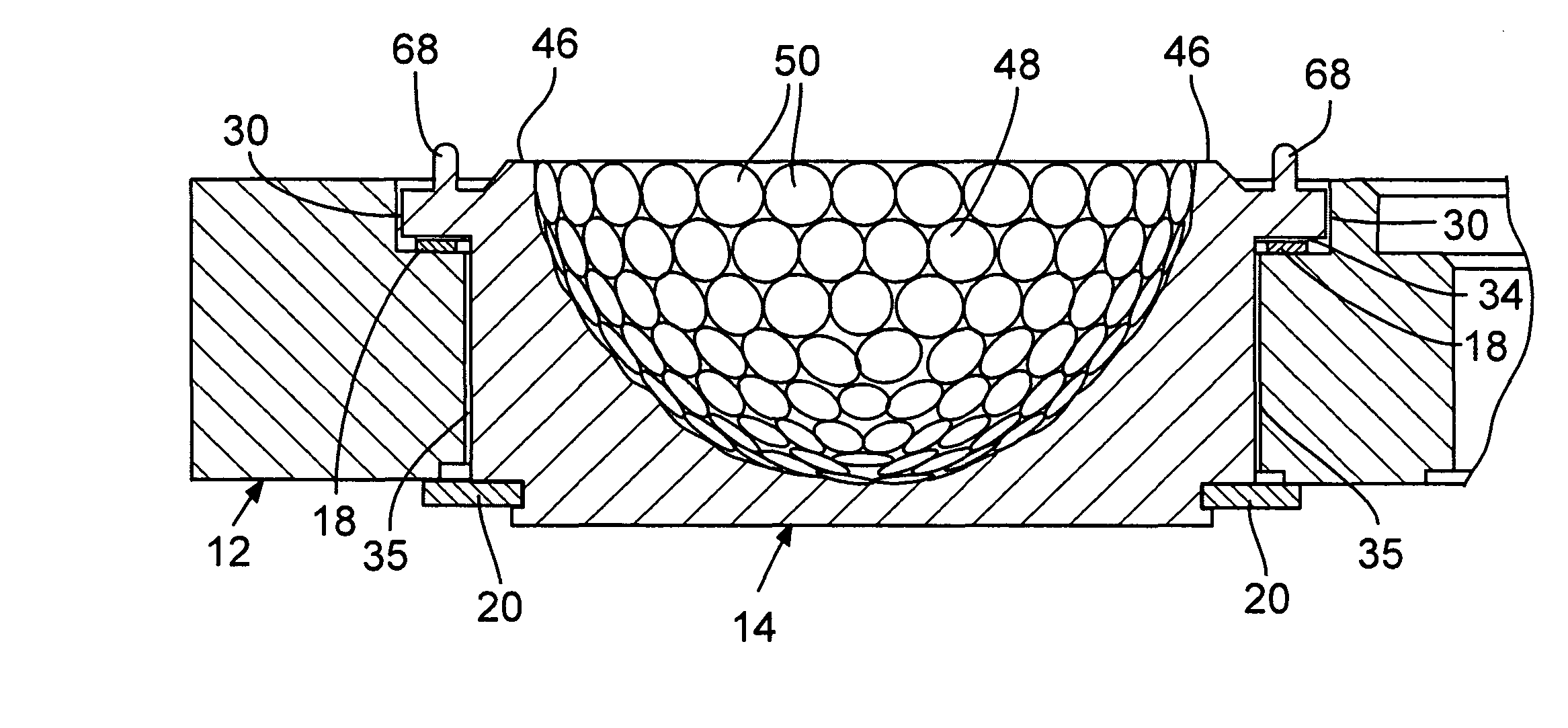
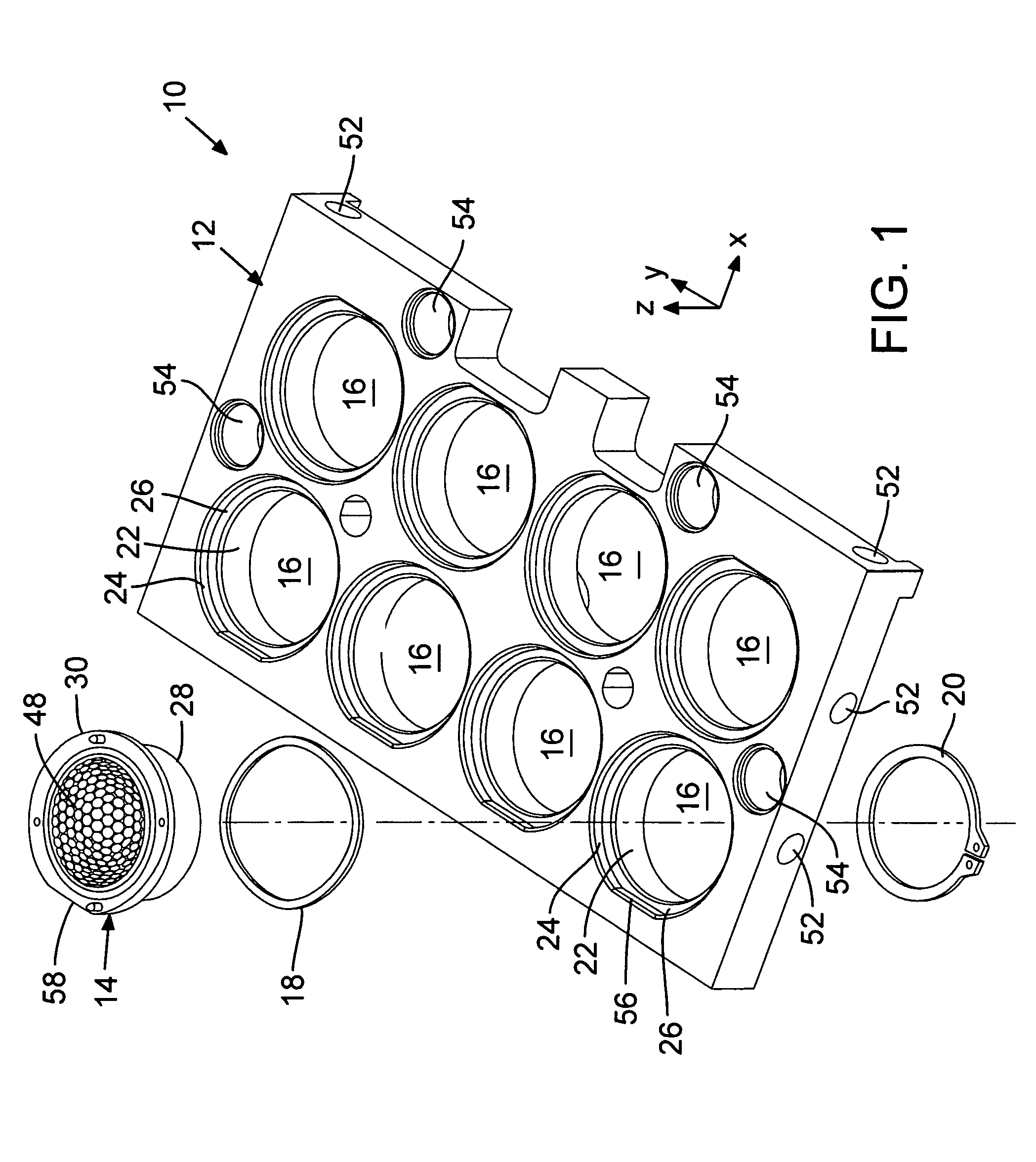
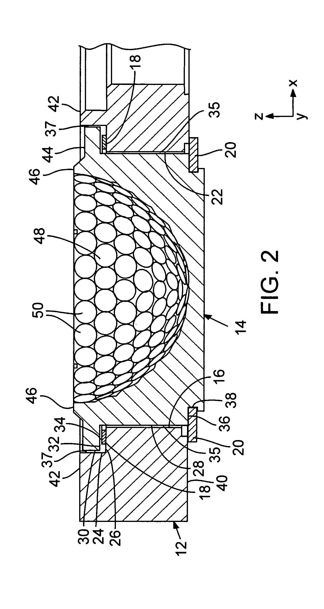
One aspect concerns mold-halves for golf-ball-cover casting molds. An embodiment of such a mold-half comprises a support member, a mold-cavity insert, a mounting, and a self-centering device. The mold-cavity insert defines a substantially hemispherical ball-cover cavity. The mounting couples the mold-cavity insert to the support member and provides floatability of the mold-cavity insert, relative to the support member, in multiple degrees of freedom (for example, and not intending to be limiting, in x, y, and z degrees of freedom). The self-centering device is associated with the mold-cavity insert and is engageable with a mating mold-cavity insert on a facing support me

Problems solved by technology

Since all three cover-molding techniques utilize, per ball, two hemispherical cavities that are brought together to form a spherical ball cavity, there is concern with events occurring at the “parting line” during molding.
Certain problems with the hemispherical cavities or with the parting surfaces, such as “offset” (axial mis-registration or axis-angular mismatch, roundness mismatch, or diametrical mismatch) of the hemispherical cavities with respect to each other or variations in the width of the parting line around the equator, is usually manifested as a corresponding anomaly on the ball cover formed in the mold.
In general, the more pronounced the surficial anomaly, the more extensive (and costly

Method used


Image

  • Golf-ball-cover casting molds with self-centering mold-cavity inserts
  • Golf-ball-cover casting molds with self-centering mold-cavity inserts
  • Golf-ball-cover casting molds with self-centering mold-cavity inserts

Examples


Example

The invention is described in the context of representative embodiments that are not intended to be limiting in any way.

As used in this application and in the claims, the singular forms “a,”“an,” and “the” include the plural forms unless the context clearly dictates otherwise. Additionally, the term “includes” means “comprises.” Further, the term “coupled” encompasses any of various ways in which one thing is linked, mounted, or attached to, and does not exclude the presence of intermediate elements between the coupled things.

In the following description, certain terms may be used such as “up,”“down,”, “upper,”“lower,”“horizontal,”“vertical,”“left,”“right,” and the like. These terms are used, where applicable, to provide some clarity of description when dealing with relative relationships. But, these terms are not intended to imply absolute relationships, positions, and / or orientations. For example, with respect to an object, an “upper” surface can become a “lower” surface simply by...


PUM

PropertyMeasurementUnit
Angleaaaaaaaaaa
Degree of freedomaaaaaaaaaa

Abstract

Molds are disclosed for forming golf-ball covers by casting. An exemplary mold includes first and second support members that are placeable in face-to-face opposition to each other. At least one respective mold-cavity insert, defining a respective hemispherical cavity, is mounted to each support member. The mold-cavity insert is floatable in at least three (e.g., x, y, z) degrees of freedom relative to the respective support member. Each mold-cavity insert on the first support member is in face-to-face opposition to a respective mold-cavity insert on the second support member whenever the support members are in face-to-face opposition to each other, such that the respective hemispherical cavities of each opposing pair of inserts form respective spherical ball-cover cavities. A respective z-direction bias is associated with each mold-cavity insert. Also, a respective self-centering device is associated with each opposing pair of inserts. The self-centering device urges movement of at least one mold-cavity insert of the opposing pair in any of at least three degrees of freedom as required to center the mold-cavity inserts of the opposing pair with each other.

Description

FIELDThis disclosure pertains to, inter alia, molds used for manufacturing golf balls. More specifically, the disclosure pertains to molds used for casting the outer layer (“cover”) of golf balls.BACKGROUNDGolf balls have undergone substantial evolution since the early days of the game. A modern golf ball 100 (see FIG. 7) is made with multiple layers, including an outer layer 102 called a “cover” and an inner body 104 called a “core.” Many modern golf balls have at least one additional layer, called a “mantle”106, situated concentrically outside the core 104. The cover 102 is typically formed around the mantle 106 so that the cover is concentric with the mantle and the mantle and core are sealed inside the cover. For purposes of description herein, the term “core” is used generally herein to denote the portion of a golf ball located inside the cover and providing the surface on which the cover is formed, regardless of whether the core comprises one or more layers.Conventional techni...

Claims


Application Information

Patent Timeline
IPC IPC(8): B29C70/70B29C33/30B29C39/10
CPCA63B37/0003A63B45/00B29C33/306B29C39/10A63B37/0075A63B37/0087B29C33/0022B29C33/30B29C33/303B29C43/027B29C43/36B29C2043/3665B29K2021/00B29L2031/54B29L2031/545
Inventor KUTTAPPA, SANJAY MUKATIRA
Owner TAYLOR MADE GOLF
Why Eureka
Try Eureka