
Autonomous inspector mobile platform

a mobile platform and inspector technology, applied in the field of robotic devices and methods, can solve the problems of increasing the cost of sewage treatment plants, infiltration and infiltration of sewer systems, outstriping the capacity of treatment plants, etc., and achieve the effect of streamlined and low cost inspection

Active Publication Date: 2011-09-20
REDZONE ROBOTICS
View PDF81 Cites 63 Cited by
  • Summary
  • Abstract
  • Description
  • Claims
  • Application Information

AI Technical Summary

Benefits of technology

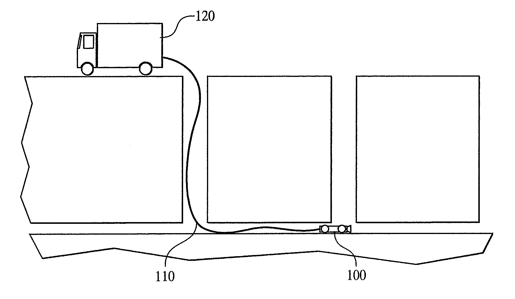
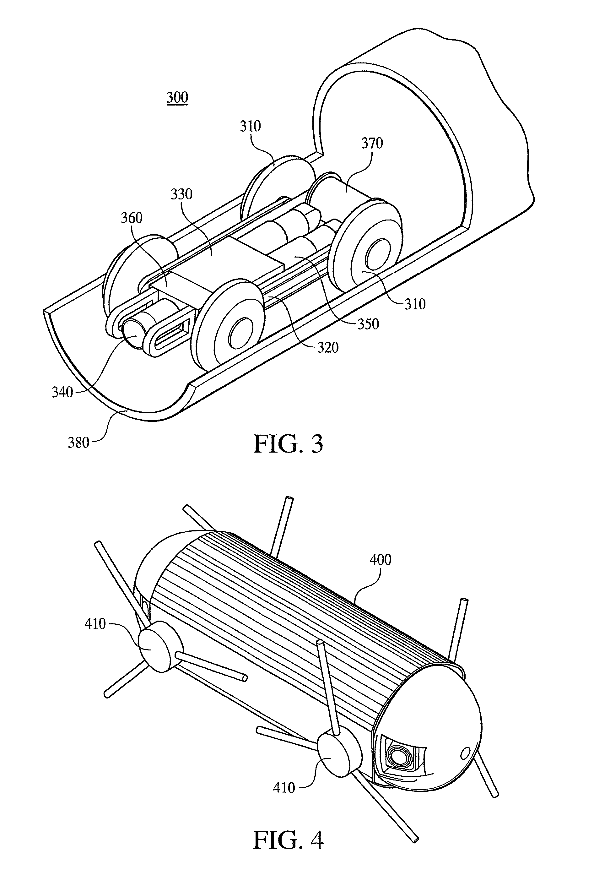
In at least one preferred embodiment, the present invention provides robotic devices and systems for allowing for the streamlined and low cost inspection and surveillance of pipes and pipe networks using trenchless methods. An autonomous robot, which may be untethered or tethered for mechanical, communications and / or power, is deployed within the pipe (for the purposes of this application, the word “pipe” includes any hollow or semi-enclosed void into which a robot may be inserted for mapping or imaging purposes). Once deployed, the robot navigates through the pipe capturing image data (either still pictures or video) at periodic intervals (or continuously) to form a complete picture or map (2D or 3D) of the interior structure of the pipe. This complete image data can then be automatically (by a computer) or manually (by a human) reviewed to determine the condition of the pipe and the existence of one or more defects that need to be addressed.
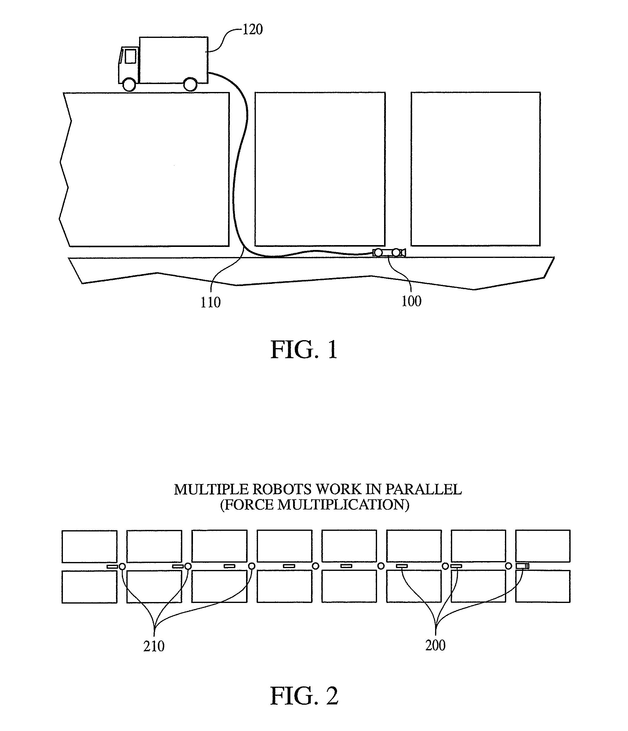
At their core, the methods of the present invention segregate the tasks of video / image collection from the task of operator review and classification—tasks that traditionally were performed in tandem. Through the use of the inexpensive and easily deployed / operated robots of the present invention, a single operator (or small team of operators) can deploy and utilize a plurality of different inspector robots at different locations (e.g., at successive sections of pipe between manholes) to simultaneously gather image data from the plurality of locations.
After data capture, computer software is then used to put together the image data from the plurality of different robots into a single, coherent pictorial description of the pipe that can be efficiently reviewed by the operator. If wide angle (“fish eye” / spherical / panospheric) lens cameras are used to capture the data, each individual image may need to be unwarped and joined with image data of adjacent portions of the pipe using known imaging techniques. Video and / or still pictures may be used alone or in combination with each other.

Problems solved by technology

A major problem in the U.S. sewer systems is inflow and infiltration (“I&I”).
I&I increases costs at sewage treatment plants, and, in a number of cases, the additional water injected during a rainstorm outstrips the capacity of treatment plants.
This often results in the diversion of raw sewage into rivers and streams.
Along the same lines, the biggest problem in the U.S. potable water system is leaky pipes.
The decay, sediment and leakage taking place in either water pipes or water storage tanks accounts for impurities in drinking water that enter the system after the water leaves the water purification plant, and prevents the satisfaction of these government regulations.
Over time these pipes deteriorate—the pipes crack and corrode and the pipe joints become dislodged—requiring replacement or refurbishment.
This often requires closing a roadway and removing the earth and pavement underneath it, which is later replaced at great cost.
Generally, old trenched methods are still employed only when specification engineers are not trained in trenchless methods or the subject pipe is so deteriorated it requires the dig and replace method (which is only required a small percentage of the time).
Although they are gaining momentum, traditional (i.e., current) trenchless pipe rehabilitation methods are quite limited.
Such systems typically cost over $100,000 and are highly specialized to the task.
The efficiency of this approach is limited by the embedding of the classification process and the platform controls within the task of collecting video data.

Method used


Image

  • Autonomous inspector mobile platform
  • Autonomous inspector mobile platform
  • Autonomous inspector mobile platform

Examples


Embodiment Construction

It is to be understood that the figures and descriptions of the present invention have been simplified to illustrate elements that are relevant for a clear understanding of the invention, while eliminating, for purposes of clarity, other elements that may be well known. Those of ordinary skill in the art will recognize that other elements are desirable and / or required in order to implement the present invention. However, because such elements are well known in the art, and because they do not facilitate a better understanding of the present invention, a discussion of such elements is not provided herein. The detailed description will be provided herein below with reference to the attached drawings.

The present invention is generally directed to an autonomous robotic camera for pipe infrastructure inspection with an optional dual use as a surveillance platform. Specifically, the autonomous inspector mobile platform (“AIMP”) is a compact, autonomous mobile robot that performs imaging a...


PUM


Abstract

An autonomous inspector mobile platform robot that is used to inspect a pipe or network of pipes. The robot includes a locomotion device that enables the device to autonomously progress through the pipe and accurately track its pose and odometry during movement. At the same time, image data is autonomously captured to detail the interior portions of the pipe. Images are taken at periodic intervals using a wide angle lens, and additional video images may be captured at locations of interest. Either onboard or offboard the device, each captured image is unwarped (if necessary) and combined with images of adjacent pipe sections to create a complete image of the interior features of the inspected pipe. Optional features include additional sensors and measurement devices, various communications systems to communicate with an end node or the surface, and / or image compression software.

Description

BACKGROUND OF THE INVENTION1. Field of the InventionThe present invention relates generally to robotic devices and methods for inspecting and mapping the interior of pipes and pipe networks, and, more specifically, the present invention is directed to autonomous pipe inspection robots that navigate through pipe networks gathering image data for forming a complete picture of the network, and methods for utilizing the same.2. Description of the BackgroundThe oldest pipes in the United States date to the late 1800's, and the average non-rehabilitated water and sewer pipe is more than 50 years old. However, depending on the type of material used, pipe operating life ranges from only 50 to 125 years. Much of the existing pipe, therefore, needs to either be replaced or rehabilitated (relined or otherwise repaired) in short order.A major problem in the U.S. sewer systems is inflow and infiltration (“I&I”). I&I is caused by the inflow of rainwater into the sewer system due to heavy rains an...

Claims


Application Information

Patent Timeline
Patent Type & Authority Patents(United States)
IPC IPC(8): G06F19/00
CPCE03F7/10F16L55/32H04N7/185G01S13/881
Inventor REVERTE, CARLOS F.THAYER, SCOTT M.WHITTAKER, WILLIAMCLOSE, ERIC C.SLIFKO, ADAMHUDSON, EDISONVALLAPUZHA, SUBRAMANIAN
Owner REDZONE ROBOTICS
Learn More