
Metal coil securing apparatus and method

a technology of metal coils and securing devices, which is applied in the directions of load securing, transportation and packaging, transportation items, etc., can solve the problems of reducing the risk of falling from the trailer, at least in part, and ensuring the safety of the securing devi

Inactive Publication Date: 2011-09-27
SEVER PAUL
View PDF13 Cites 7 Cited by
  • Summary
  • Abstract
  • Description
  • Claims
  • Application Information

AI Technical Summary

Benefits of technology

"The patent describes a metal coil securing device and method for safely securing metal coils to a flatbed transport trailer. The device is designed to be easily attached to the metal coil while on the ground, allowing for easy loading onto the trailer. The device includes a coil cover and tie down straps that are secured to the coil with hook and loop fasteners. The method involves securing the coil cover to the metal coil, loading the coil onto the trailer, and securing the tie down straps to the coil to secure it in place. The device helps to reduce risks associated with drivers climbing onto the flatbed trailer to perform securement tasks. The use of lightweight yet sturdy materials makes the device easier to use and meets industry standards. The device can be easily attached to the metal coil and is designed to be easily removed and replaced."

Problems solved by technology

As a result, the disclosed metal coil securing device ameliorates at least in part the risks associated with drivers climbing onto a flatbed transport trailer to perform conventional securement and tarping tasks practiced in the prior art.
However, throughout the unloading process the driver and other personnel are not required to mount the flatbed transport trailer for unloading operations and thereby be at risk of falling from the flatbed trailer.

Method used


Image

  • Metal coil securing apparatus and method
  • Metal coil securing apparatus and method
  • Metal coil securing apparatus and method

Examples


Embodiment Construction

[0027]For purposes of the description hereinafter, spatial orientation terms, if used, shall relate to the referenced embodiment as it is oriented in the accompanying drawing figures or otherwise described in the following detailed description. However, it is to be understood that the embodiments described hereinafter may assume many alternative variations and configurations. It is also to be understood that the specific devices, features, and components illustrated in the accompanying drawing figures and described herein are simply exemplary and should not be considered as limiting.

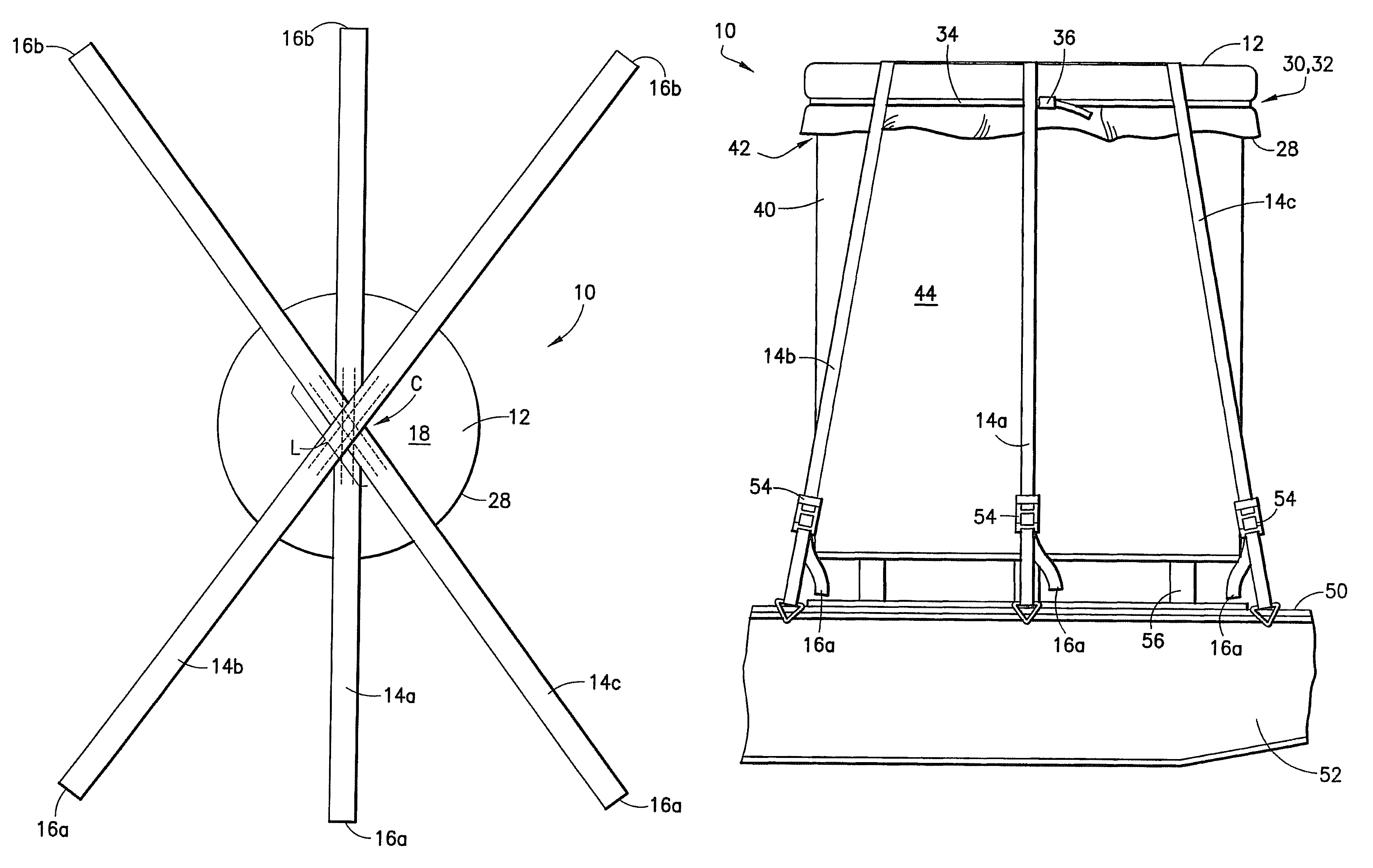
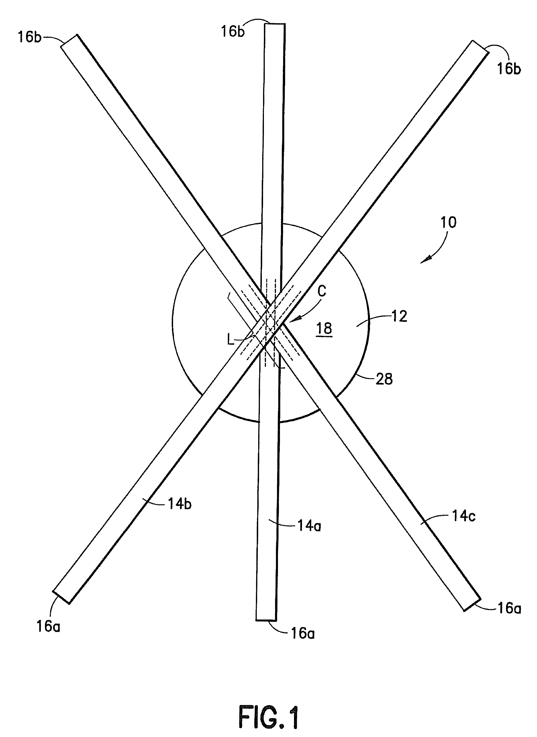
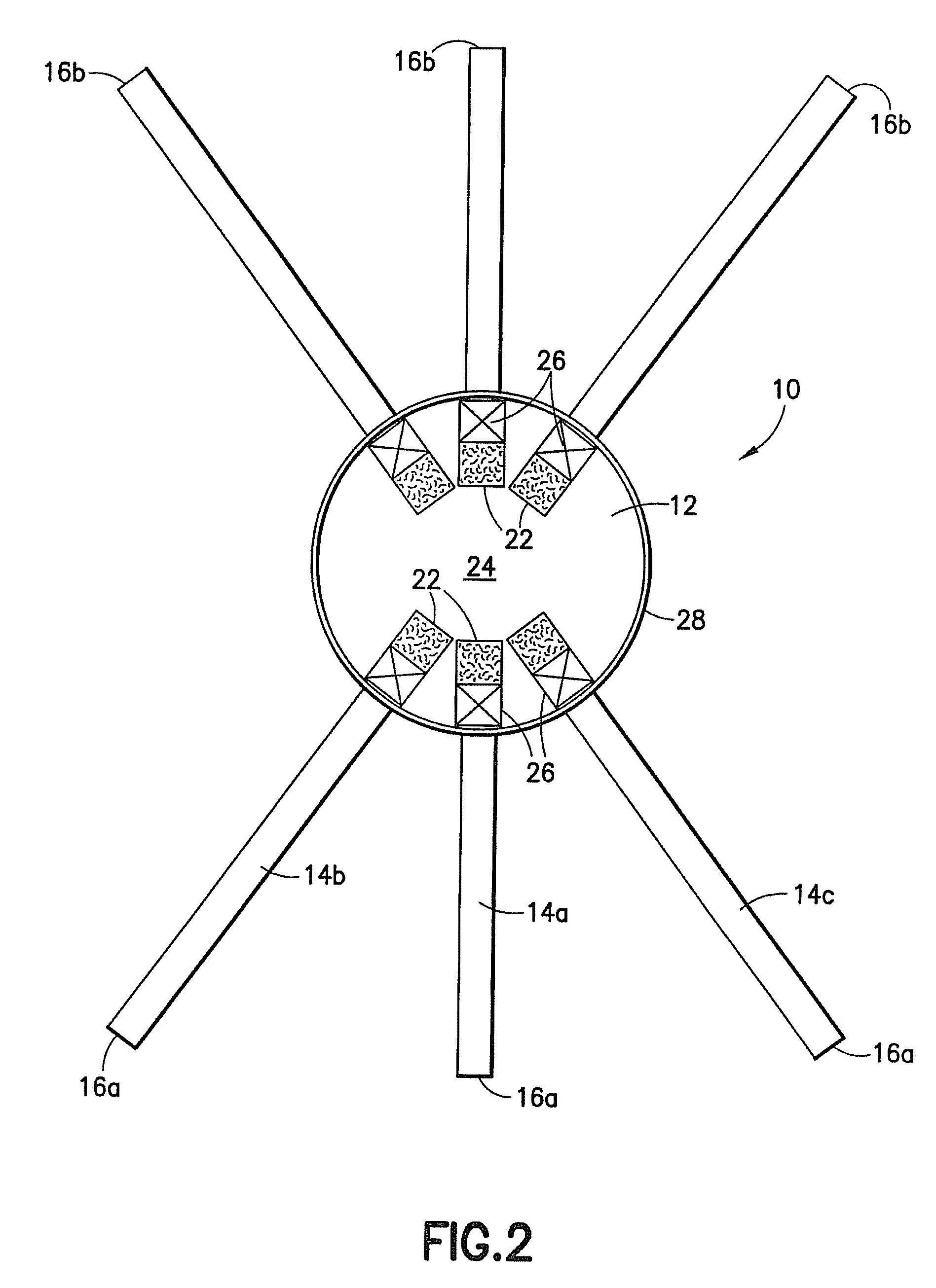
[0028]An embodiment of a metal coil securing device 10 is shown in FIGS. 1-2 and is used to secure a metal coil 40 to a flatbed platform 50 of a transport trailer 52. Securing device 10 typically comprises a coil cover 12 adapted to encompass at least a portion of metal coil 40. In one form, coil cover 12 is generally circular shaped and formed of flexible sheet material such as nylon tarp material. Coil...


PUM


Abstract

A metal coil securing device is disclosed including a coil cover adapted to encompass a metal coil and a plurality of tie down straps affixed to the coil cover, with each tie down secured along a portion of its length to the coil cover such that each tie down has two free ends extending outward from the periphery of the coil cover. In one embodiment, the tie down straps are secured to a circular coil cover to intersect at an approximate center of the coil cover and extend radially outward therefrom. A method of securing a metal coil to a transport trailer is also disclosed generally including associating and securing the coil cover with the metal coil, loading the metal coil with the secured coil cover onto the transport trailer, and using the free ends of the tie down straps to secure the metal coil to the transport trailer.

Description

BACKGROUND OF THE INVENTION[0001]1. Field of the Invention[0002]An objective of the invention described herein relates to providing a device and method of securing metal coils to a flatbed trailer and desirably from ground level thereby obviating the need for anyone to be on the trailer itself at any time during the securing process.[0003]2. Description of Related Art[0004]In the standard practice of securing metal coils to flatbed transport trailers, truck drivers and other persons often have to climb onto the flatbed to accomplish securing and tarping operations. This raises the possibility of injury as the truck driver and others may fall of the flatbed portion of the transport trailer and sustain injury and, in extreme circumstances, even death. Shippers have recognized the risk and safety concerns and in some cases have installed fall protection devices on the flatbed portion of the transport trailer often at an enormous expense. Some of known fall protection systems include me...

Claims


Application Information

Patent Timeline
Patent Type & Authority Patents(United States)
IPC IPC(8): B60P7/08
CPCB60P7/0823B60P7/0876
Inventor SEVER, PAUL
Owner SEVER PAUL
Learn More