
Frequency response optimisation of a movement simulator by adaptive sinusoidal reference tracking

a technology of reference tracking and frequency response, applied in adaptive control, process and machine control, instruments, etc., can solve the problems of limited maximum value of cut-off frequency, more tracking error becomes significant, and the robustness necessary in the control loop provides limitations for the performance of this control law

Active Publication Date: 2011-09-27
EXAIL
View PDF2 Cites 0 Cited by
  • Summary
  • Abstract
  • Description
  • Claims
  • Application Information

AI Technical Summary

Benefits of technology

[0044]Preferably still the means to determine the numerator Rr(z−1) also takes as an input parameter the value of the frequency of sa

Problems solved by technology

But this test is only valid if the movement simulator has effectively a movement which follows the reference signal.
Conversely, the more the frequency of the sinusoidal reference increases, the more the tracking error becomes significant.
Nevertheless the maximal value of the cut-off frequency is limited because of the high frequency dynamics which cannot be taken into account in the modelling of the controlled machine, a modelling on which the synthesis of the control law is based.
However, from a theoretical viewpoint, robustness and performances are proved to be two antagonistic notions.
I.e. the robustness necessary in the control loop provides limitations for the performances of this control law, and in particular lowers the cut-off frequency of this control law.
All the known control systems used on the current movement simulators are subject to such constraint.
The movement simulators being machines designed for metrology, this attenuation and this phase-shift cause great difficulties for accurate characterisation of the components to be tested.

Method used


Image

  • Frequency response optimisation of a movement simulator by adaptive sinusoidal reference tracking
  • Frequency response optimisation of a movement simulator by adaptive sinusoidal reference tracking
  • Frequency response optimisation of a movement simulator by adaptive sinusoidal reference tracking

Examples


Embodiment Construction

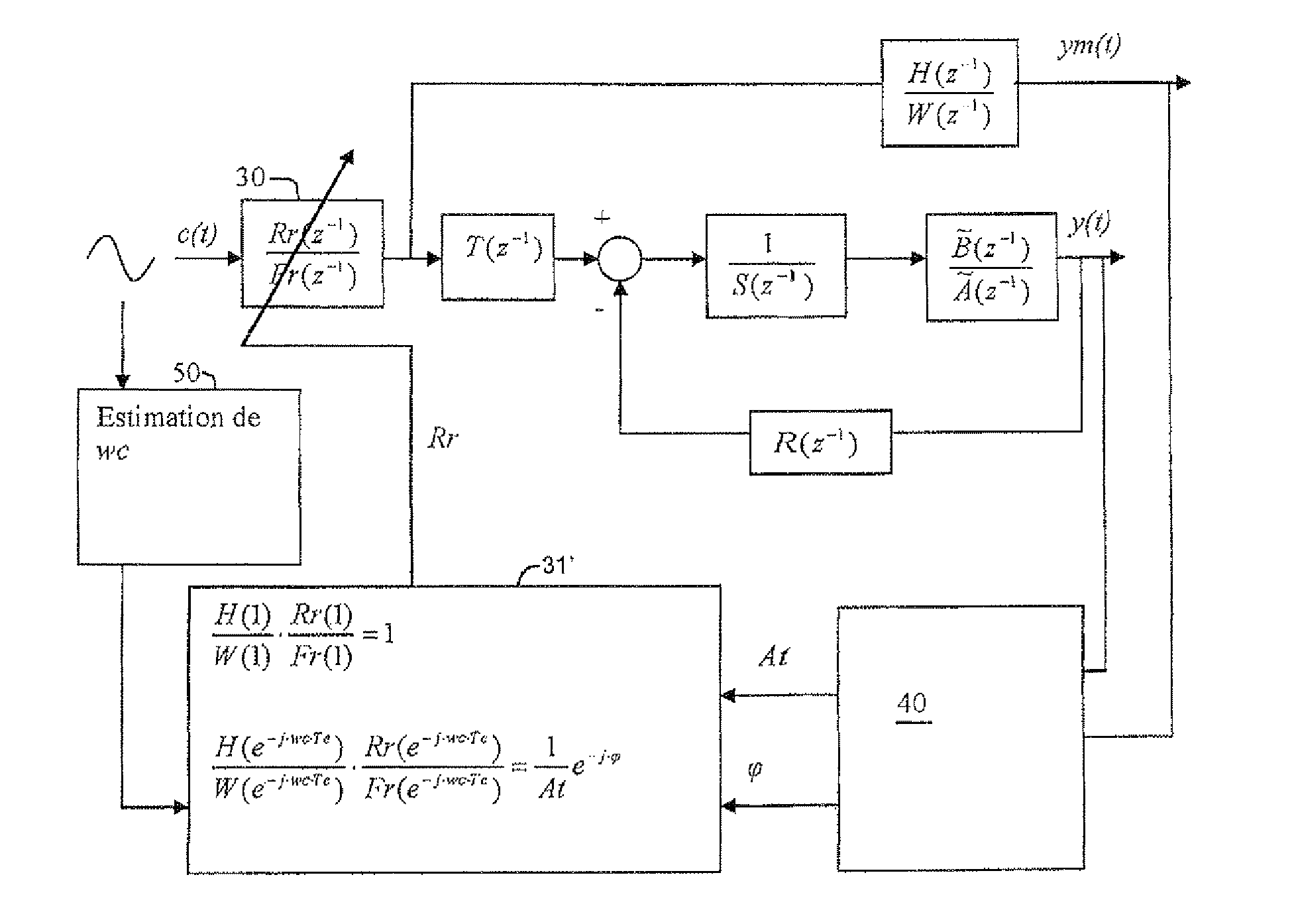
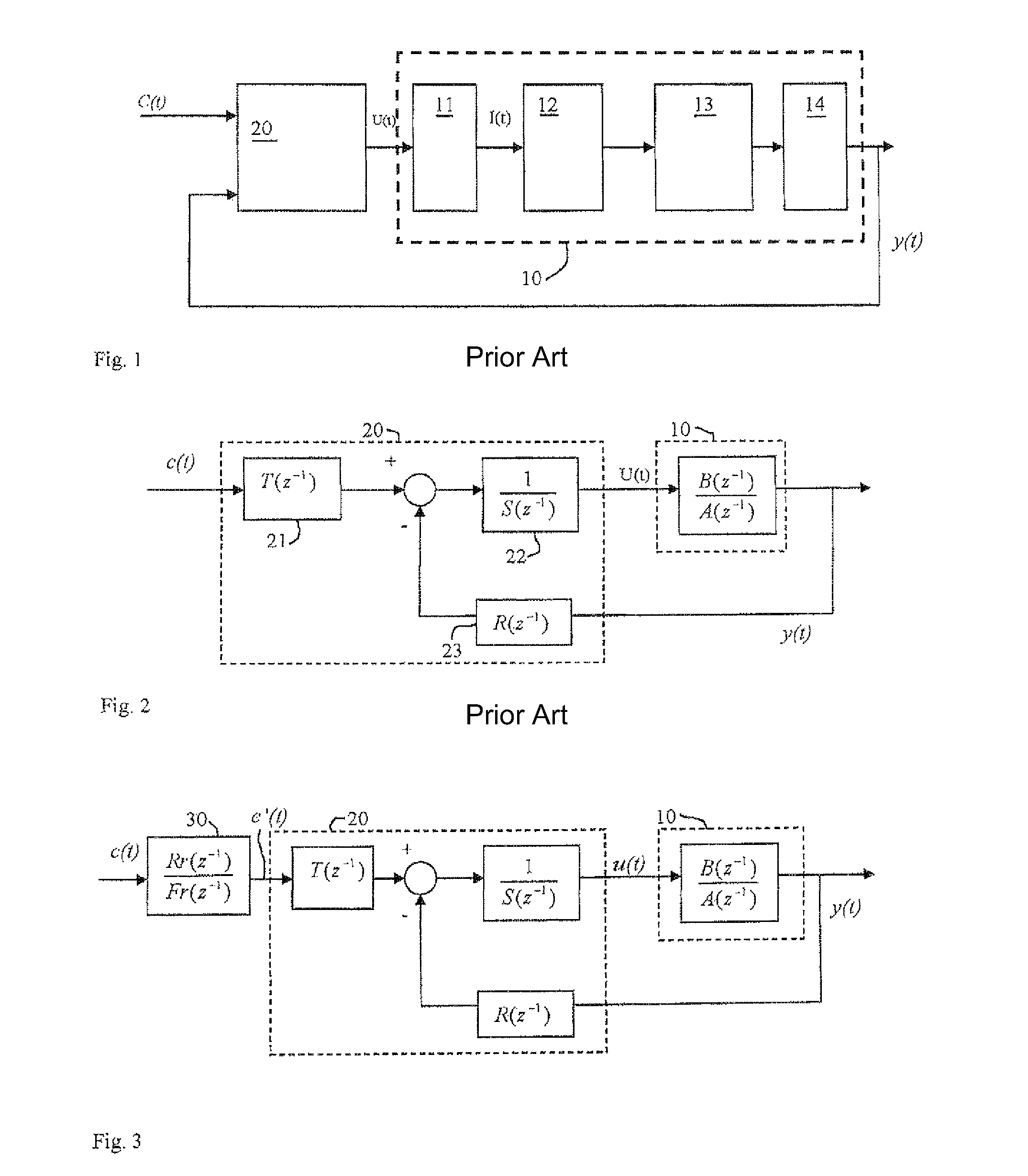
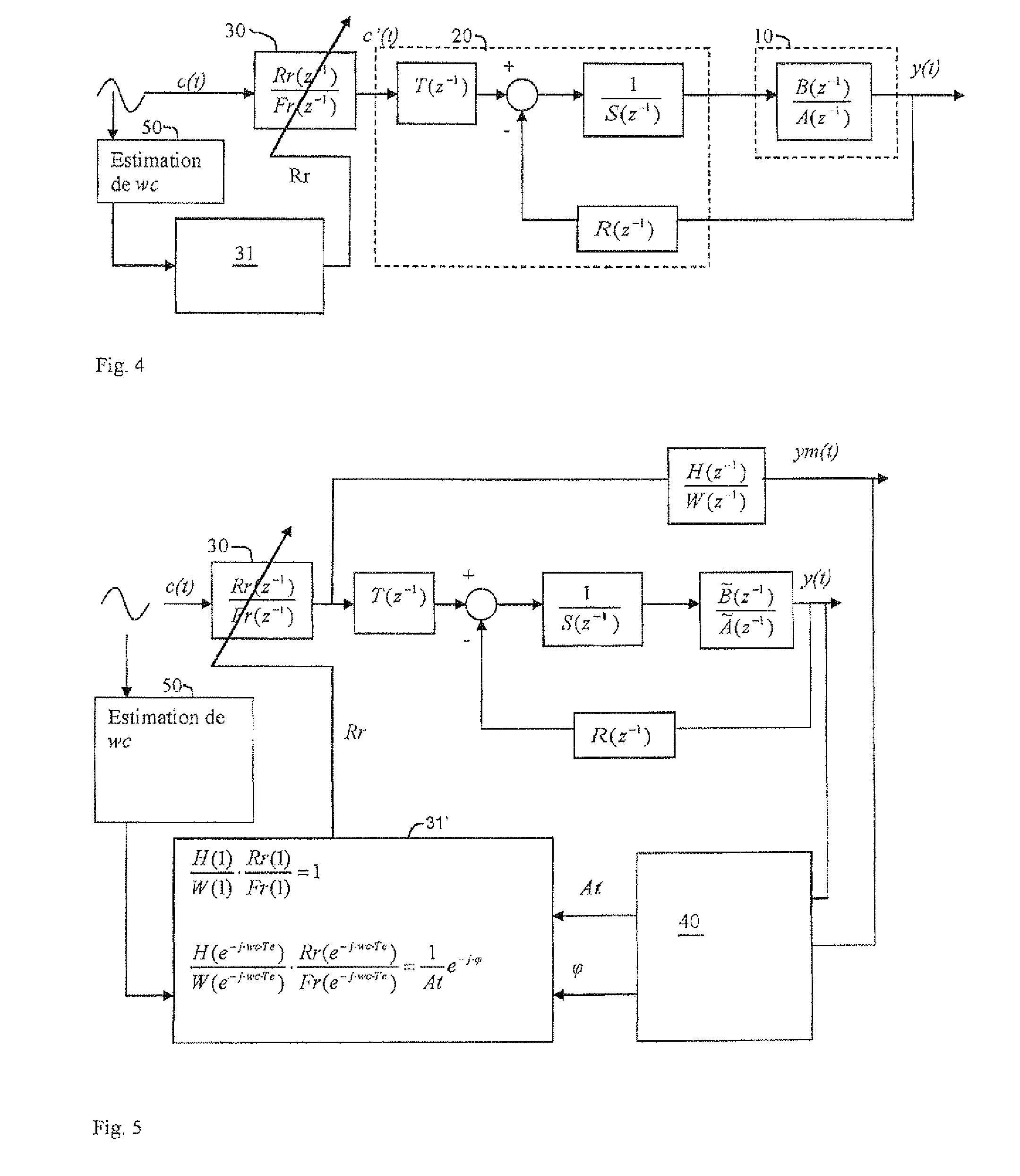
[0054]The block diagram of a closed loop is given very generally by FIG. 2. The system 10 to be controlled is modelled by a discrete transfer function G, sampled with the period Te:

[0055]G⁡(z-1)=B⁡(z-1)A⁡(z-1)(1)

[0056]In the equation (1), z=ej·w·Te represents the “advance of a sampling period” operator.

[0057]The corrector or command law 20 is represented as an RST forms (corrector with two degrees of freedom), which is the most general representation of a monovariable corrector. It can be seen that any linear monovariable corrector may be as an RST form. In particular the correctors of the PID type, monovariable LQG-LTR, Hinfini, Crone, etc. may be written as an RST form. The present invention is hence not limited to the RST correctors. The structure of the RST controller is represented diagrammatically in detail on FIG. 2 by the blocks 21 to 23.

[0058]The transfer function between the reference c(t) and the measurement y(t) is written as follows:

[0059]y⁡(t)c⁡(t)=T⁡(z-1)⁢B⁡(z-1)A⁡(z-...


PUM


Abstract

The control device of a movement simulator, between its input formed of a control signal and its output formed of a measured magnitude among its speed, its position and its acceleration, by a transfer function B(z−1) / A(z−1) includes a corrector synthesized from the modelling of the movement simulator and equivalent to a RST controller. The controller includes a reference input, a retro-action input whereon is applied the measured magnitude and an output producing the control signal. The transfer function between the reference input of the controller and the measured magnitude is H(z−1) / W(z−1). The device has a reference filter whose input is a sinusoidal reference signal c(t) at a frequency wc and applying at output a filtered reference signal on the reference input of the controller. The reference filter has a transfer function Rr(z−1) / Fr(z−1), whose denominator and numerator are adapted to ensure, for the frequency wc, effective tracking by the movement simulator of the sinusoidal reference.

Description

CROSS-REFERENCE TO RELATED APPLICATIONS[0001]The instant Application claims benefit of priority and incorporates by reference French Application 0752807 filed Jan. 22, 2007.STATEMENT REGARDING FEDERALLY SPONSORED RESEARCH OR DEVELOPMENT[0002]Not Applicable.THE NAMES OF THE PARTIES TO A JOINT RESEARCH AGREEMENT[0003]Not Applicable.INCORPORATION-BY-REFERENCE OF MATERIAL SUBMITTED ON A COMPACT DISC[0004]Not ApplicableBACKGROUND OF THE INVENTION[0005]1. Field of the Invention[0006]The invention relates to movement simulators controlled in position, in speed or in acceleration.[0007]2. Description of Related Art[0008]The movement simulators are used, among other things, for testing the frequency response of a component laid on the table top of a movement simulator capable of generating movements such as instantaneous rotational movements around an axis. A particularly interesting category of movements for conducting tests is formed of movements such as the position, the speed or the angu...

Claims


Application Information

Patent Timeline
IPC IPC(8): G06F7/60G06F17/10
CPCG05B13/042G05B17/02
Inventor VAU, BERNARD
Owner EXAIL
Learn More