
Injection molding machine

a molding machine and injection molding technology, applied in the field of injection molding machines, can solve the problems of generating assembling errors in the mold mounting process, difficult alignment of the mold center with the center of the supporting plate when the molds are mounted to the supporting plate, and difficulty in mounting the molds to correct positions, so as to achieve the effect of minimizing the defects of molded products

Inactive Publication Date: 2011-10-04
SAMSUNG ELECTRONICS CO LTD
View PDF17 Cites 3 Cited by
  • Summary
  • Abstract
  • Description
  • Claims
  • Application Information

AI Technical Summary

Benefits of technology

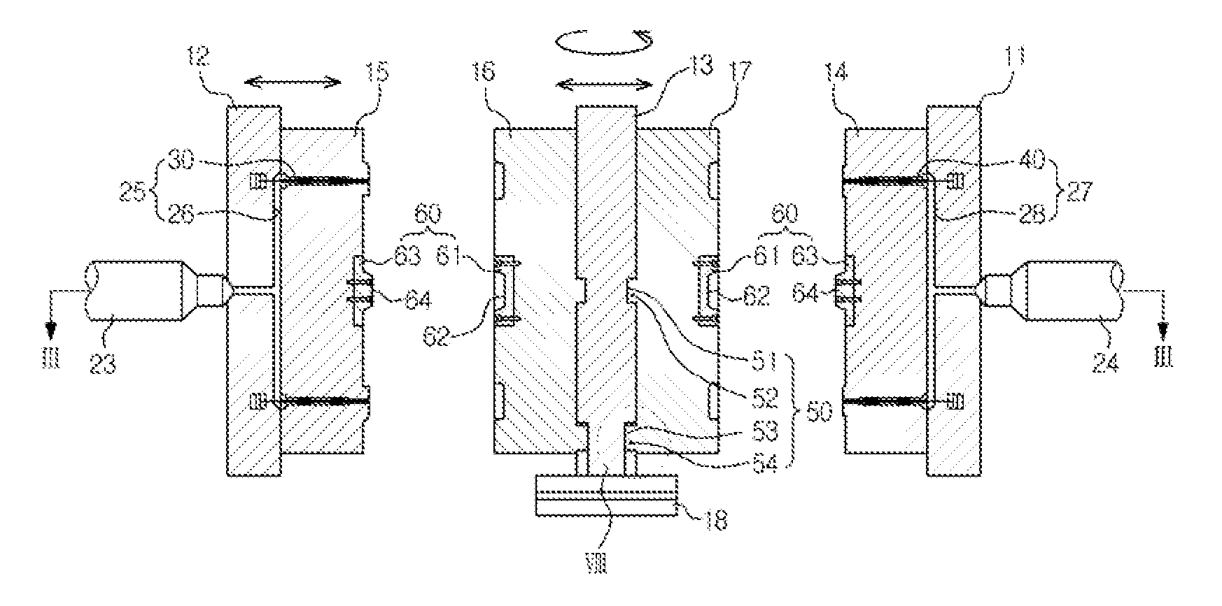
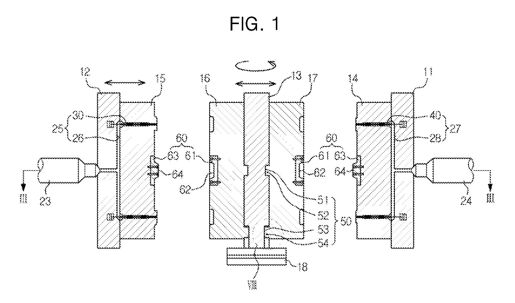
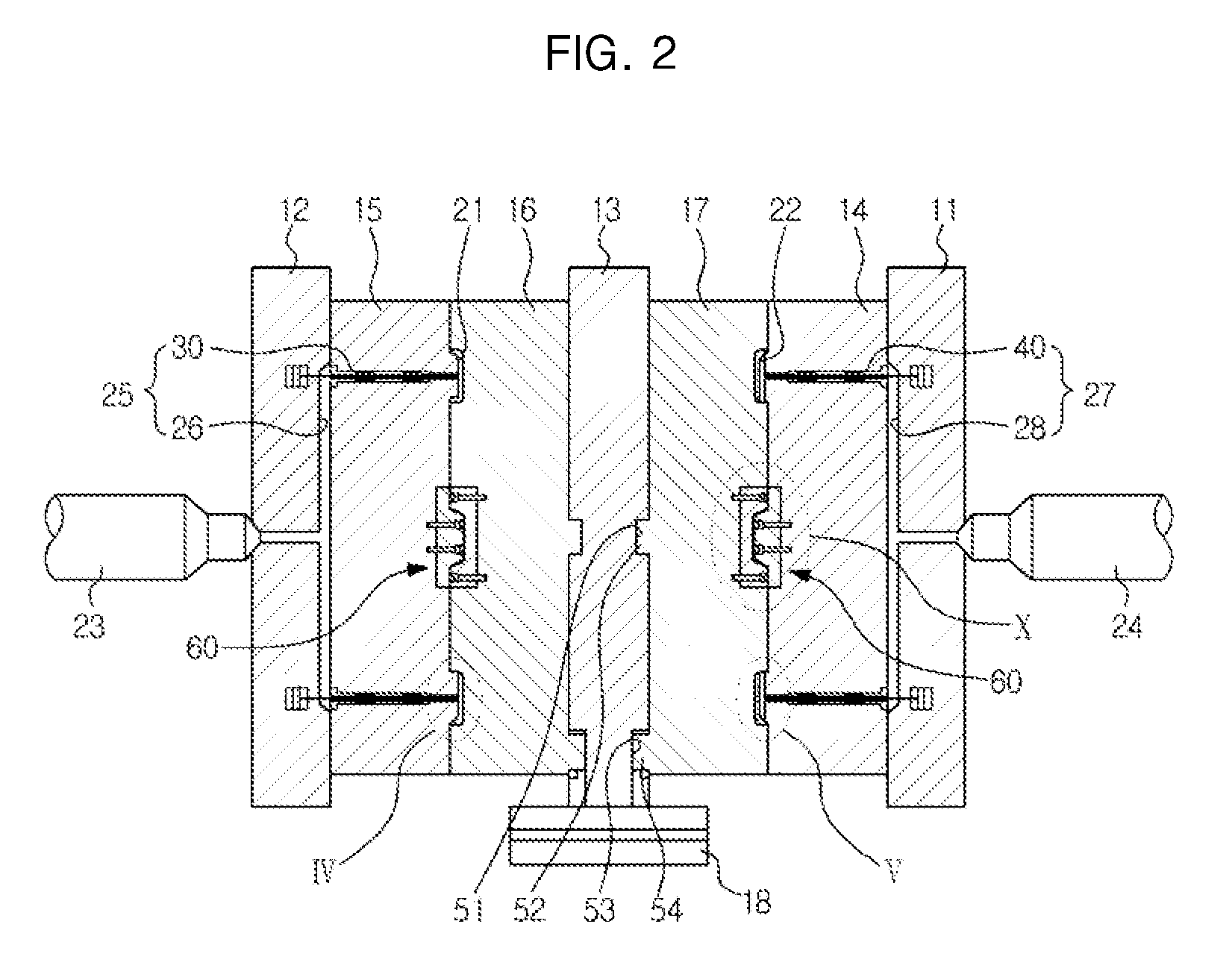
[0009]The present general inventive concept provides an injection molding machine to minimize defects of molded products by accurately aligning centers of molds assembled with each other.
[0010]The present general inventive concept also provides an injection molding machine to mount molds to correct positions when the molds are coupled to supporting plates, and of accurately keeping the coupling positions even when the molds are thermally deformed.

Problems solved by technology

However, in the above conventional injection molding machine, because moving the heavy molds is difficult, aligning centers of the molds with centers of the supporting plates when the molds are mounted to the supporting plates is difficult.
Also, because the centers of the molds may deviate from the centers of the supporting plates in the process of tightening the bolts, mounting the molds to correct positions is difficult.
Also, if the molds are thermally deformed, assembling errors may be generated in the mold mounting process.
The assembling errors of the molds may cause a problem of misalignment of the centers of the molds assembled with each other, and as a result may create defects of molded products.

Method used


Image

  • Injection molding machine
  • Injection molding machine
  • Injection molding machine

Examples


Embodiment Construction

[0038]Reference will now be made in detail to exemplary embodiments of the present general inventive concept, examples of which are illustrated in the accompanying drawings, wherein like reference numerals refer to like elements throughout. The embodiments are described below to explain the present general inventive concept by referring to the figures.

[0039]An injection molding machine according to an embodiment of the present general inventive concept, as illustrated in FIG. 6, can produce a double molded product 1 which includes a transparent layer 2 and a colored layer 3. The double molded product 1 illustrated in FIG. 6 is used for a front case of a display apparatus (e.g., TV, monitor or the like) or a cellular phone, and has an opened center portion so as to expose a screen. However, a molded product produced by the injection molding machine according to an embodiment of the present general inventive concept is not limited to the above-described shape.

[0040]As illustrated in F...


PUM

PropertyMeasurementUnit
shapeaaaaaaaaaa
temperatureaaaaaaaaaa
moldingaaaaaaaaaa

Abstract

An injection molding machine includes supporting plates, molds coupled to the supporting plates, and a coupling guide device to guide the coupling of the molds and the supporting plates. The coupling guide device includes a first coupling guide recess and a first coupling guide protrusion provided at center portions of the molds and the supporting plates so as to be coupled to each other, and a second coupling guide recess and a second coupling guide protrusion provided at the molds and the supporting plates, spaced apart from the first coupling guide recess and the first coupling guide protrusion, so as to be coupled to each other. The second coupling guide recess is formed lengthwise in a direction toward a periphery from the center portions of the molds and the supporting plates.

Description

CROSS-REFERENCE TO RELATED APPLICATIONS[0001]This application claims priority under 35 U.S.C. §119(a) from Korean Patent Application No. 2008-0031791, filed on Apr. 4, 2008 in the Korean Intellectual Property Office, the disclosure of which is incorporated herein in its entirety by reference.BACKGROUND OF THE INVENTION[0002]1. Field of the Invention[0003]The present general inventive concept relates to an injection molding machine, and more particularly, to an injection molding machine having a guide device to guide coupling of molds and supporting plates and assembling of the molds.[0004]2. Description of the Related Art[0005]An injection molding machine is a machine that produces a molded product by injecting molten resin into a cavity defined by molds at a high pressure and solidifying the resin.[0006]An injection molding machine generally includes molds to define a cavity, supporting plates to support the molds, and a high pressure cylinder to inject molten resin into the cavity...

Claims


Application Information

Patent Timeline
Patent Type & Authority Patents(United States)
IPC IPC(8): B29C45/22
CPCB29C33/303B29C45/1743B29C33/30B29C45/26B29C45/64
Inventor CHOI, DUCK SULEE, SHANG HANKANG, HAN MOOGKIM, JAE HYUNG
Owner SAMSUNG ELECTRONICS CO LTD
Learn More