Model predictive control system and method for reduction of steady state error

a control system and model technology, applied in the field of control systems, can solve problems such as increasing the cost of one or more variables, and achieve the effect of reducing the steady state error

Active Publication Date: 2011-10-04
ROCKWELL AUTOMATION TECH
View PDF43 Cites 104 Cited by
  • Summary
  • Abstract
  • Description
  • Claims
  • Application Information

AI Technical Summary

Benefits of technology

[0005]The present invention provides a technique for reducing steady state error in model predictive control systems designed to respond to such needs. The technique may be used in any suitable control system, including those used in industrial applications, commercial applications, vehicles, manufacturing applications, and so forth. The technique does not require offsets or alteration of basic control models, although it may be used conjunction with systems that permit such adaptability.
[0006]In general, the present technique is based upon the detection of a steady state error between a forward looking prediction of a variable and a desired value for the variable. The steady state error is generally detected over a persistence time to avoid adapting or responding to the error unnecessarily. If a steady state error is detected and persists for a threshold time, a value of the model predictive control algorithm is modified to reduce the error. In particular, the modification may consist of increasing a cost for one or more variables that are not at the desired level or that influence the variable that is not at the desired level. The modification may be made in a cost or objective function implemented by the system, such as in a coefficient of one or more variables. The technique may effectively modify the coefficient based upon an integral of the difference between the controlled variable and a desired level over a forward looking control horizon. When this integral value is large, the coefficient in the cost function is large, thus driving the value to the desired level. The integral is forward-looking due to the predictive nature of the model predictive control scheme. As the error is reduced, the coefficient causing the error to be reduced is naturally reduced as well.

Problems solved by technology

In particular, the modification may consist of increasing a cost for one or more variables that are not at the desired level or that influence the variable that is not at the desired level.

Method used


Image

  • Model predictive control system and method for reduction of steady state error
  • Model predictive control system and method for reduction of steady state error
  • Model predictive control system and method for reduction of steady state error

Examples


Embodiment Construction

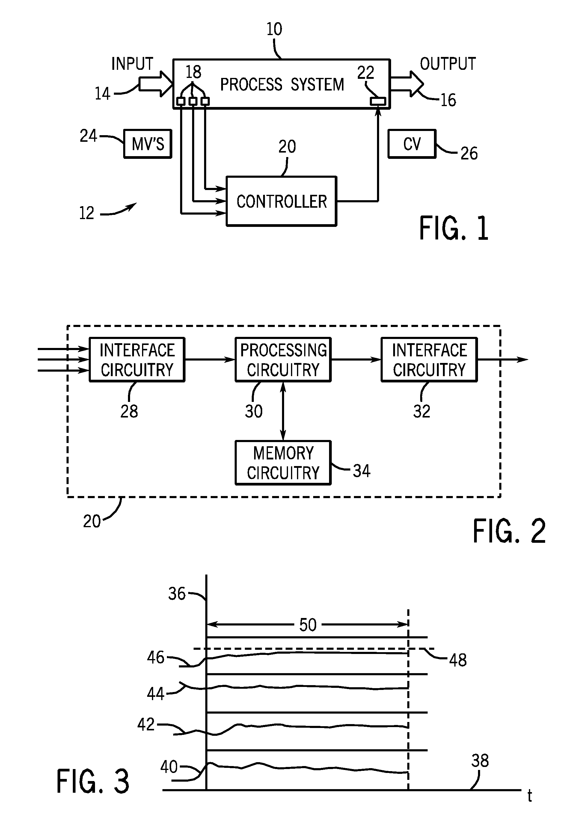
[0014]Turning now to the drawings, and referring first to FIG. 1, a process system 10 is illustrated that is at least partially regulated by a control system 12. As will be appreciated by those skilled in the art, the process system 10 may be any conceivable type of process, such as a manufacturing process, a steady state or batch process, a chemical process, a material handling process, an engine or other energy utilizing process, an energy production process, and so forth. In general, the process system 10 will receive one or more inputs 14 and produce one or more outputs 16. In complex processes found in the industry, many such inputs may be utilized, including feed stocks, electrical energy, fuels, parts, assemblies and sub-assemblies, and so forth. Outputs may include finished products, semi-finished products, assemblies, manufacturing products, by products, and so forth. Based upon the system dynamics, the physics of the system and similar factors, the control system 12 will r...


PUM

PropertyMeasurementUnit
temperaturesaaaaaaaaaa
pressuresaaaaaaaaaa
flow ratesaaaaaaaaaa

Abstract

A technique is disclosed for reducing an error in a controlled variable via model predictive control. A predicted error in the controlled variable is determined for a forward-looking control horizon based upon measured or computed variables. The integral of the predicted error is computed. If the error or the integral exceed a tolerance for a determined time period, the model predictive control algorithm is modified to drive the error or the integral to within a tolerance. The modifications to the control algorithm may include changes to coefficients for terms based upon the error and / or the integral of the error.

Description

CROSS REFERENCE TO RELATED APPLICATIONS[0001]This application is a Non-Provisional Application of U.S. Provisional Application No. 60 / 946,879, entitled “Optimization-Based integral Control for Nonlinear Model Predictive Control and Applications”, filed Jun. 28, 2007, which is herein incorporated by reference.BACKGROUND[0002]The present invention relates generally to control systems, and more particularly to model predictive control employing novel techniques for driving a steady state error to within a desired tolerance.[0003]Many applications are known throughout industry for various types of control systems, and various control system designs fill such applications. In general, feedback control systems provide for sensing one or more detectable parameters of a process, and drive a controlled variable to a desired level on the basis of the sensed parameters. The basis for such control system design may be parametric models, neural networks, linear and non-linear models, to name onl...

Claims


Application Information

Patent Timeline
Patent Type & Authority Patents(United States)
IPC IPC(8): G05B13/02G05B19/42G05B11/01G01N15/08G05B19/00G05B15/00
CPCG05B13/048
Inventor SAYYAR-RODSARI, BIJAN
Owner ROCKWELL AUTOMATION TECH
Why Eureka
Try Eureka