Vehicle seats

a technology for vehicles and seats, applied in the field of vehicles, can solve the problems of not producing upward moments on the end portions of the seat support, and achieve the effects of preventing deformation or damage, and effectively enduring for

Inactive Publication Date: 2011-10-11
TOYOTA SHATAI KK
View PDF10 Cites 23 Cited by
  • Summary
  • Abstract
  • Description
  • Claims
  • Application Information

AI Technical Summary

Benefits of technology

[0013]According to the vehicle seat thus constructed, when a large external (inertial) force is applied to a child seat attached to the seat main body using the anchor members, the force can be effectively transmitted to the seat support via the anchor members, the anchor frame and the reinforcement members. That is, the force cannot substantially be transmitted to the side frame elements of the cushion frame. This means that the force can substantially be transmitted to a central portion of the seat support and not to end portions thereof. That is, no upward moments can be produced on the end portions of the seat support. Therefore, the seat support can withstand the force, so as to be prevented from being deformed or damaged. As a result, the seat main body can be effectively prevented from moving in the vehicle seat. That is, the seat main body can be prevented from moving with respect to the vehicle floor. Therefore, the child seat attached to the seat main body can be reliably restrained or immobilized with respect to the vehicle floor. Thus, an occupant (baby or infant) sitting on the child seat can be reliably restrained or immobilized with respect to the vehicle floor.
[0014]Further, the seat support can be effectively held by the vertically moving mechanism because the rear portion of the seat support is capable of engaging the vertically moving mechanism. Therefore, when the force is transmitted to the seat support, the seat support can further effectively withstand the force, so as to be further prevented from being deformed or damaged.

Problems solved by technology

That is, no upward moments can be produced on the end portions of the seat support.

Method used


Image

  • Vehicle seats
  • Vehicle seats
  • Vehicle seats

Examples


Embodiment Construction

[0029]In the following, a detailed representative embodiment of the present invention will be described with reference to FIG. 1 to FIG. 11.

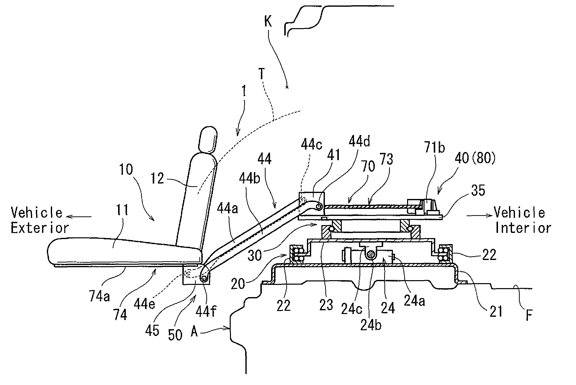
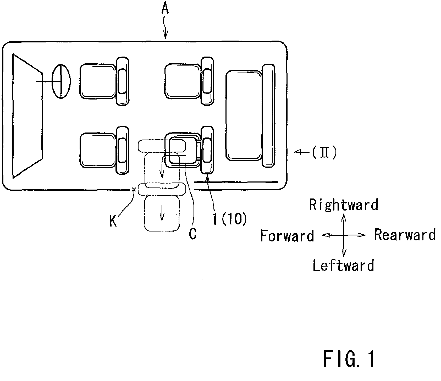
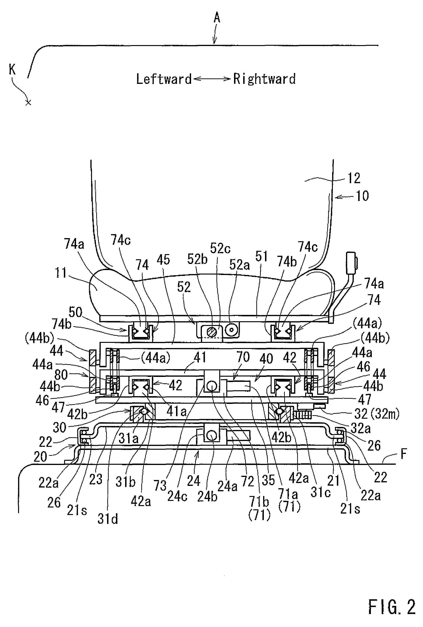
[0030]As shown in FIG. 1, a rear (second row) left seat of a vehicle A is exemplified as a vehicle seat 1 according to the representative embodiment. The vehicle seat 1 may preferably include a seat main body 10. In the vehicle seat 1, the seat main body 10 can horizontally move or rotate through an angle of 90 degrees between a forwardly facing position (shown by solid lines in FIG. 1) where it faces forwardly of the vehicle A and a laterally facing position (shown by broken lines in FIG. 1) where it faces a door opening K of the vehicle A. Further, the seat main body 10 can laterally move at the laterally facing position, so as to move between vehicle interior and vehicle exterior via the door opening K (FIGS. 3 and 4). Further, the seat main body 10 can vertically move (i.e., move up and down) in the vehicle exterior, so as to move between an...


PUM


Abstract

A vehicle seat may include a seat main body having a seat cushion, a rotation mechanism that is arranged and constructed to horizontally rotate the seat main body with respect to a vehicle floor, a vertically moving mechanism that is arranged and constructed to vertically move the seat main body while moving the seat main body between vehicle interior and vehicle exterior, and a seat support that is capable of attaching the seat main body to the vertically moving mechanism. A cushion frame of the seat cushion is composed of a pair of longitudinal side frame elements, an anchor frame positioned between the side frame elements and anchor members attached to the anchor frame. The anchor frame is connected to the seat support via reinforcement members.

Description

[0001]This application claims priority to Japanese patent application serial number 2007-249144, the contents of which are incorporated herein by reference.BACKGROUND OF THE INVENTION[0002]This invention relates to a vehicle seat. More particularly, the present invention relates to a vehicle seat suitable for a welfare vehicle in which an elderly person, a physically handicapped person or other such persons (hereinafter simply referred to as “occupant”) is capable of easy getting in and out of a vehicle.[0003]A vehicle seat is taught by, for example, Japanese Laid-Open Patent Publication No. 2005-14672. This vehicle seat includes a seat main body having a seatbelt, a first sliding mechanism that is capable of slide the seat main body in forward and rearward directions of a vehicle with respect to a vehicle floor, and a rotation mechanism that is capable of horizontally rotating the seat main body through an angle of 90 degrees between a forwardly facing position where it faces a fro...

Claims


Application Information

Patent Timeline
Patent Type & Authority Patents(United States)
IPC IPC(8): B60N2/04A47C1/08B60N2/24
CPCB60N2/14B60N2/245B60N2/2893B60N2002/0256B60N2/0256
Inventor MIURA, KAZUYAHIRAKAWA, TOMOYAHIBI, KAZUHIRO
Owner TOYOTA SHATAI KK
Why Eureka
Try Eureka