Spiral membrane module

a membrane module and spiral technology, applied in the direction of membranes, other chemical processes, separation processes, etc., can solve the problems of large pressure loss of the permeate-side channel, risk of contaminating water quality, and cumbersome operation of the engagement connection or the operation of the connection release, so as to facilitate the connection with each other

Active Publication Date: 2011-10-11
NITTO DENKO CORP +1
View PDF12 Cites 9 Cited by
  • Summary
  • Abstract
  • Description
  • Claims
  • Application Information

AI Technical Summary

Benefits of technology

[0015]According to the present invention, a movable member having an engagement part is provided as a connection mechanism that restrains the relative displacement of adjacent membrane elements with each other, and the movable member has a contact part coming into contact with the inner wall of the pressure vessel and looking the engagement. Therefore, by simply allowing the membrane elements to be received into the pressure vessel in a state in which the engagement part is engaged, the membrane elements can be easily connected with each other, and moreover the connection is not loosened or released during the operation.
[0016]In the above, the above-described connection mechanism is preferably provided with a release mechanism that releases the engagement by the above-described engagement part in a state in which the above-described contact part is not in contact with the inner wall. With this construction, by simply allowing the membrane elements to be received into the pressure vessel, the membrane elements can be easily connected with each other and, conversely, by simply taking the membrane elements out from the pressure vessel, the connection between the membrane elements can be released.
[0017]Also, the above-described movable member is preferably a lever member having a flexible part that releases the above-described engagement by elastic restoration force. With this construction, the engagement and the release of the engagement part can be carried out with a simple structure by deformation of the flexible part.
[0018]Further, the above-described upstream-side end part and the above-described downstream-side end part that are connected each preferably have a guide inclination part that guides the engagement part of the above-described movable member to the engagement part of the opposite side by relative rotation of the two. By providing a guide inclination part each in the above-described upstream-side end part and the above-described downstream-side end part, the engagement part is guided because relative rotation is generated by the guide inclination part when the two are made to abut against each other and pressed into the pressure vessel even in a state in which the positions of the engagement parts with each other is shifted a little, whereby the engagement of the two can be carried out smoothly.

Problems solved by technology

Since this results in the abrasion of the O-ring 35, leakage is generated from the feed side to the permeate side, thereby inviting a risk of contaminating the water quality.
As a result thereof, there arises a problem of large pressure loss of the permeate-side channel.
This raises a problem in that, according as the engagement part of the telescope prevention member is made less liable to be loosened, the operation of the engagement connection or the operation of the connection release will be more cumbersome.

Method used


Image

  • Spiral membrane module
  • Spiral membrane module
  • Spiral membrane module

Examples


Embodiment Construction

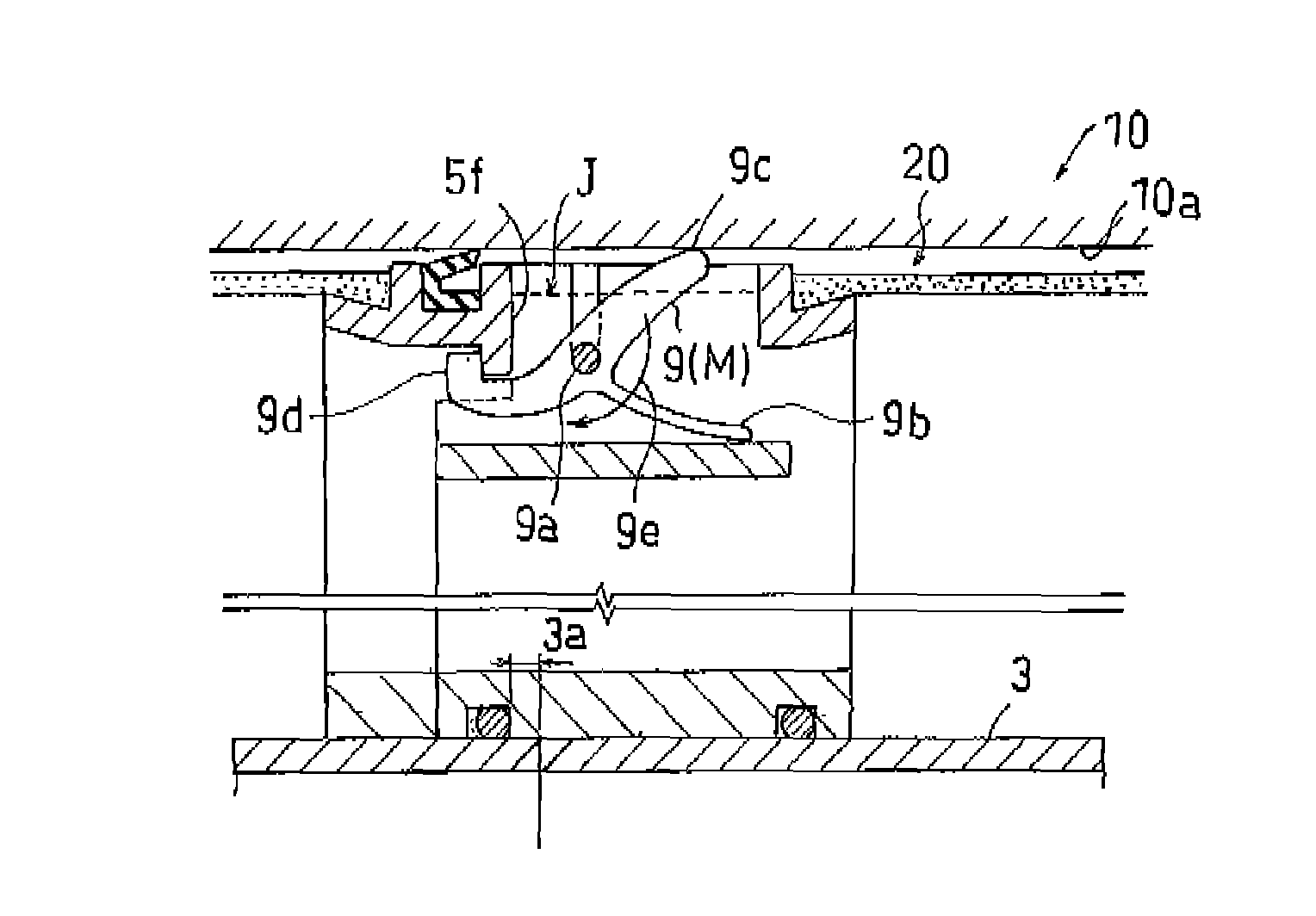
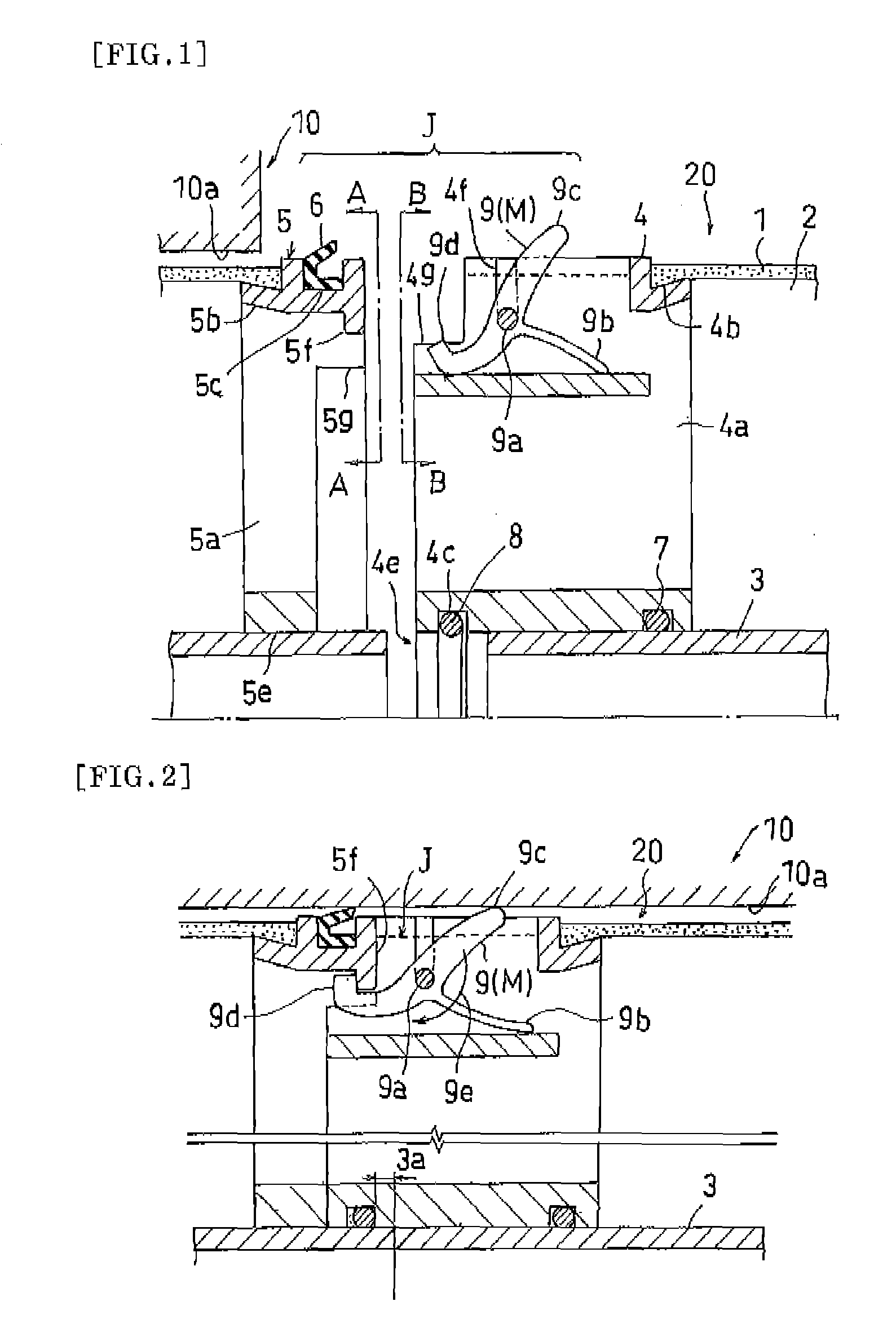
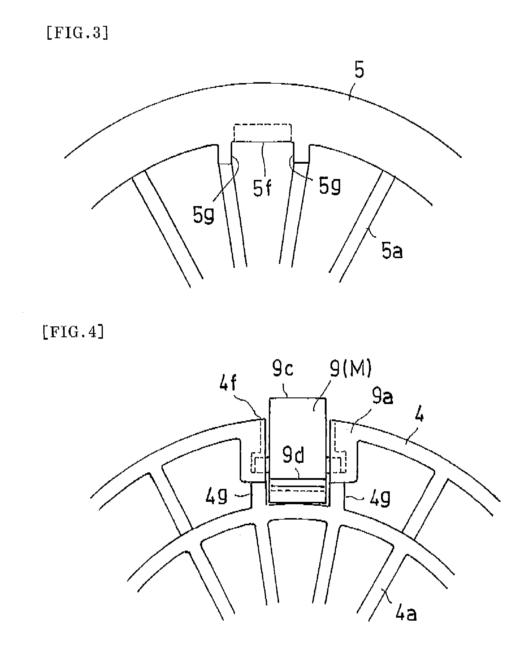
[0070]Hereinafter, embodiments of the present invention will be described with reference to the drawings. FIG. 1 is a cross-sectional view of an essential part showing one example of a connection mechanism of a spiral membrane module of the present invention (non-connected state), and FIG. 2 shows a connected state thereof. In addition, FIG. 3 is an enlarged view of the essential part showing an A-A arrow view in FIG. 1, and FIG. 4 is an enlarged view of the essential part showing a B-B arrow view. Note that, for simplifying the description, some parts have been illustrated by being subjected to enlargement, shrinkage, or the like.

[0071]As shown in FIG. 2, the spiral membrane module of the present invention is such that a plurality of spiral membrane elements 20 (hereinafter referred to as “membrane elements”) each formed in multiple layers by winding membranes and channel materials around a center tube 3 having holes are received in a pressure vessel 10 while being connected in ser...


PUM

PropertyMeasurementUnit
flexibleaaaaaaaaaa
relative rotationaaaaaaaaaa
elastic restoration forceaaaaaaaaaa

Abstract

A spiral membrane module where membrane elements are easily connected to each other and the connection thereof is prevented from being loosened. The spiral membrane elements (20) are each formed in multiple layers by winding membranes and channel materials around a center tube (3) having holes and are received in a pressure vessel (10) such that they are connected in series with connection mechanisms (J) placed between the membrane elements (20). Each connection mechanism (J) has a movable member (M) installed at either the upstream side end part or the downstream side end part of each membrane element (20) and having an engagement part (9d) engageable with the other of the upstream side end or the downstream side end. The movable member (M) has a contact part (9c) coming into contact with the inner wall (10a) of the pressure vessel (10) and locking the engagement by the engagement part (9d).

Description

[0001]This application is the U.S. National Phase under 35 U.S.C. §371 of International Application No. PCT / JP2006 / 325470, filed Dec. 21, 2006, which claims priority to the Japanese Patent Application No. 2005-370208, filed Dec. 22, 2005. The International Application was not published in English under PCT Article 21(2).TECHNICAL FIELD[0002]The present invention relates to a spiral membrane module in which a plurality of spiral membrane elements for separating components dissolved or otherwise present in liquid are connected through the intermediary of a connection mechanism and received in a pressure vessel.BACKGROUND ART[0003]A spiral membrane module generally has a structure such that a plurality of spiral membrane elements are connected and received in a pressure vessel (See, for example, Patent Document 1). This separation membrane element has, as a basic structure thereof, a structure such that a single or a plurality of laminates of separation membrane units made of a two-fol...

Claims


Application Information

Patent Timeline
Patent Type & Authority Patents(United States)
IPC IPC(8): B01D63/10B01D63/00
CPCB01D63/106B01D63/12B01D2313/02B01D2313/04B01D63/10B01D63/00B01D2313/041
Inventor BEPPU, MASASHIUDA, YASUHIROCHIKURA, SHINICHIYAMAMOTO, KENTARO
Owner NITTO DENKO CORP
Why Eureka
Try Eureka