Suspension device

a suspension device and spring technology, applied in the direction of spring/damper, mechanical apparatus, transportation and packaging, etc., can solve the problems of reducing the force further and the constant of the spring, and achieve the effect of reducing the reaction force tending, and reducing the relative displacement between the leaves upon deflecting the leaves

Active Publication Date: 2012-05-29
HINO MOTORS LTD +1
View PDF14 Cites 0 Cited by
  • Summary
  • Abstract
  • Description
  • Claims
  • Application Information

AI Technical Summary

Benefits of technology

[0014]Thus, any relative displacement between the spring leaves upon deflecting of the same may be accommodated by shear strain of the interplate rubber members, so that a great frictional resistance is not produced unlike the conventional metal-to-metal contact to substantially reduce the reaction force tending to constrain the relative displacement of the spring leaves.
[0015]The respective upper and lower spring leaves have the paired curved portions formed longitudinally oppositely and symmetrically with the different curvature radii and vertically unaligned bend starts and bend ends so that relative displacement between the leaves is reduced upon deflecting of the leaves.
[0016]Since the reaction force, which tends to constrain the relative displacement between the spring leaves, is calculated as multiplication of the relative displacement between the leaves by the spring constant of the interplate rubber members, the reduction in the relative displacement between the leaves causes the reaction force to be reduced further in comparison with mere interposition of the interplate rubber members, so that spring leaves become easily deflectable, resulting in reduction of the spring constant.
[0017]It has been also confirmed that not only the spring constant is reduced but also dynamic characteristics of the spring leaves are also substantially improved, which makes the spring leaves easily deflectable at their deflection starts and deflection ends, resulting in even softer comfort of the vehicle ride.

Problems solved by technology

Since the reaction force, which tends to constrain the relative displacement between the spring leaves, is calculated as multiplication of the relative displacement between the leaves by the spring constant of the interplate rubber members, the reduction in the relative displacement between the leaves causes the reaction force to be reduced further in comparison with mere interposition of the interplate rubber members, so that spring leaves become easily deflectable, resulting in reduction of the spring constant.

Method used


Image

  • Suspension device
  • Suspension device
  • Suspension device

Examples


Embodiment Construction

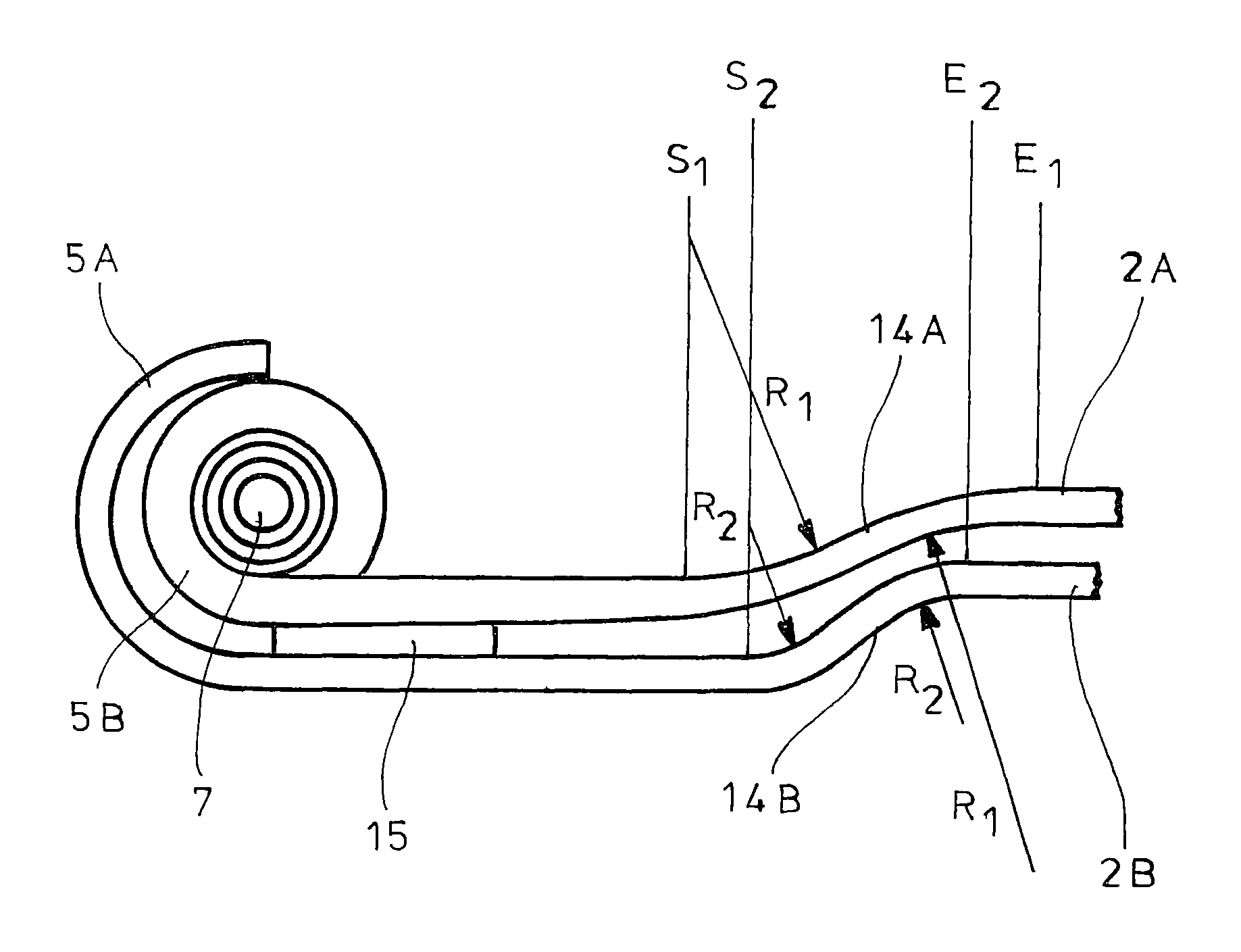
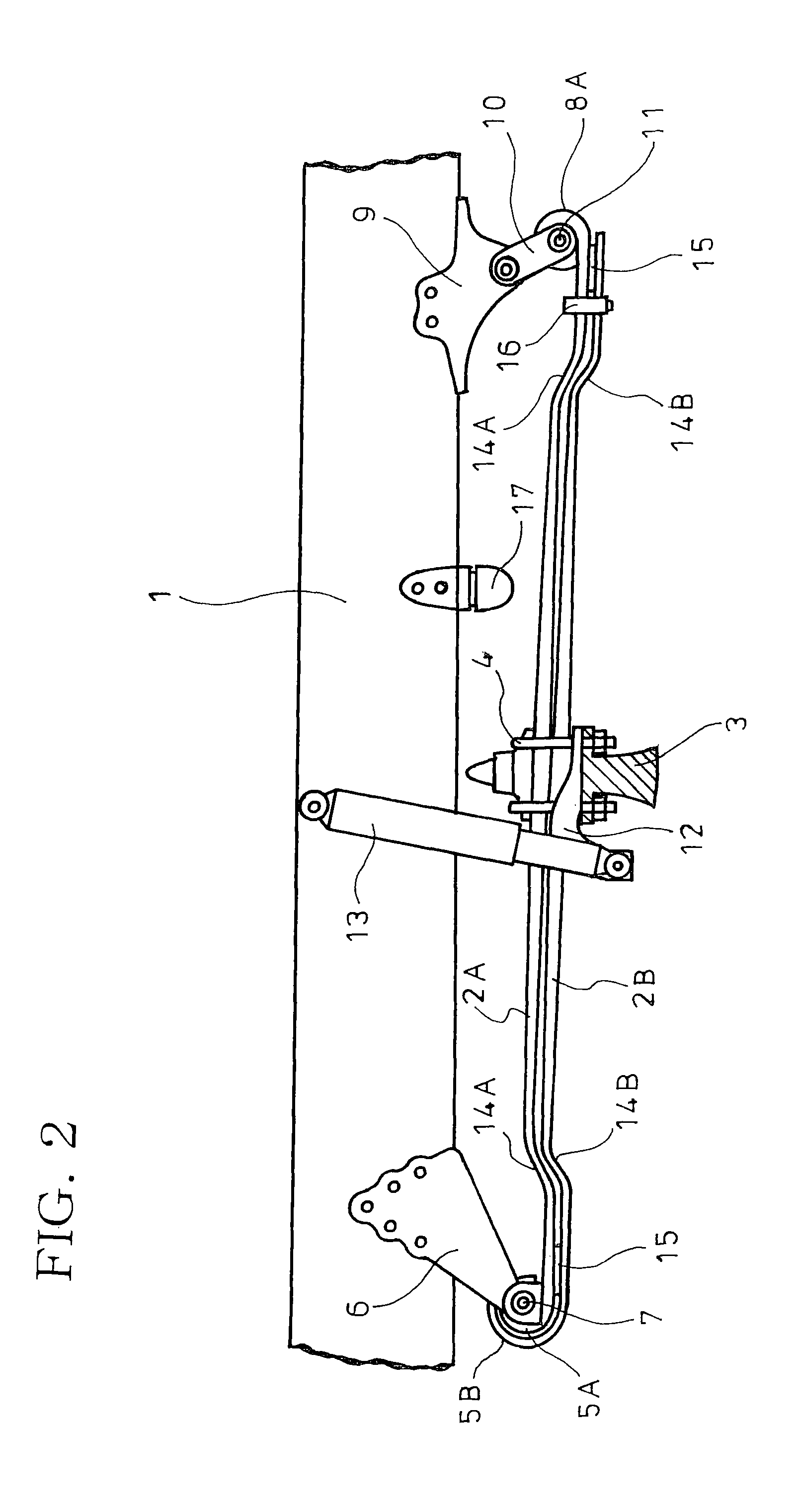
[0026]FIGS. 2-6 show an embodiment of the invention in which parts similar to those in FIG. 1 are represented by the same reference numerals.

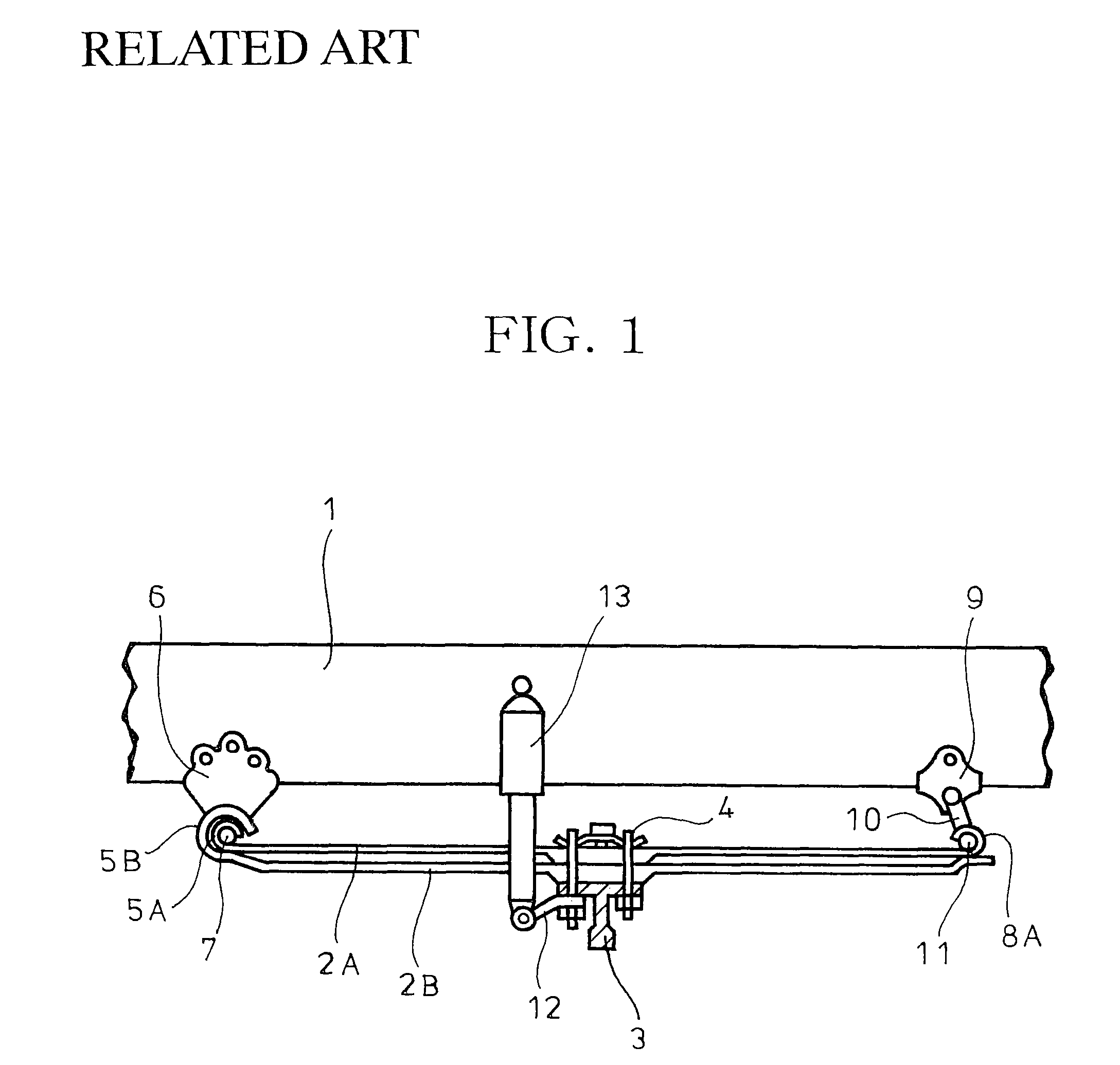
[0027]As shown in FIGS. 2 and 3, in the embodiment, just like the related art shown in FIG. 1, an axle 3 is suspended from a side rail 1 by upper and lower laminated spring leaves 2A and 2B and is connected from below to longitudinally intermediate portions of the spring leaves 2A and 2B, using U-bolts 4. A tip end of a bracket 12 which is also fixed at the portions, using the U-bolts 4, is connected to the side rail 1 arranged just above the bracket 12 by a shock absorber 13.

[0028]Front ends of the spring leaves 2A and 2B are upwardly wound into eyes 5A and 5B for pivotal motion via a rubber bush (not shown) about a spring pin 7 of a front bracket 6 secured to the side rail 1. A rear end of the upper spring leaf 2A is wound upwardly, just like its front end, into an eye 8A for pivotal motion via a rubber bush (not shown) with a spring pin 11 o...


PUM


Abstract

Interplate rubber members 15 are interposed between abutting front and rear ends of spring leaves 2A and 2B. The spring leaves 2A and 2B have paired curved portions 14A and 14B, respectively, which are symmetrically S-shaped with respect to a connected position of an axle 3 in side view. A curvature radius of continuous and mutually reverse curves of each of the curved portions 14A of the upper spring leaf 2A is greater than a curvature radius of continuous and mutually reverse curves of each of the curved portions 14B of the lower spring leaf 2B. The upper curved portions 14A have longitudinally outward bend starts longitudinally outward of longitudinally outward bend starts of the lower curved portions 14B and have longitudinally inward bend ends longitudinally inward of longitudinally inward bend ends of the lower curved portions 14B.

Description

BACKGROUND OF THE INVENTION[0001]1. Field of the Invention[0002]The present invention relates to a suspension device.[0003]2. Description of the Related Art[0004]Among various devices for suspension of axles from a frame, a suspension device comprising laminated spring leaves has been prevailing for vehicles such as trucks since it is simple in structure, inexpensive in cost, high in strength and highly durable.[0005]FIG. 1 shows a conventional leaf-spring suspension device in which reference numeral 1 denotes a pair of left and right side rails extending longitudinally or in a fore-and-aft direction of a vehicle and providing part of a chassis frame; 2A and 2B, laminated spring leaves arranged along each of the side rails 1; and 3, an axle in the form of a beam member. The axle 3 is connected from below to longitudinally intermediate portions of the spring leaves 2A and 2B, using U-bolts 4.[0006]The spring leaves 2A and 2B have front ends upwardly wound into eyes 5A and 5B, respect...

Claims


Application Information

Patent Timeline
Patent Type & Authority Patents(United States)
IPC IPC(8): B60G11/12F16F1/28
CPCB60G11/04F16F1/185F16F1/26B60G2202/112
Inventor ENOMOTO, MITSURUNAKAMURA, KAORUFUKUNAGA, KOKO
Owner HINO MOTORS LTD
Why Eureka
Try Eureka