Deformable cap for a computer pointing device

a technology of pointing device and deformation cap, which is applied in the field of deformation cap for computer pointing device, can solve the problems of unobstructed access of the operator, and achieve the effects of less force, increased contact surface area, and increased friction between the cap and the operator's fingertip

Inactive Publication Date: 2011-10-11
IBM CORP
View PDF5 Cites 6 Cited by
  • Summary
  • Abstract
  • Description
  • Claims
  • Application Information

AI Technical Summary

Benefits of technology

[0011]The problems outlined above are in large part addressed by a deformable cap for a miniature joystick-type computer pointing device. When an operator applies a finger to an upper surface of the cap, the cap deforms such that the surface area of contact between the cap and the operator's finger is increased. After the finger is removed from the cap, the original shape of the cap is recovered. Preferably, the operator's finger is only required to apply a weak force to deform the cap. Additionally, the cap may be made such that it has a concave shape when deformed ...

Problems solved by technology

If the pointing device is placed within a keyboard, the deformed cap may cover a portion of one or more keys of the keyboard when an operator's finger is on the cap; however,...

Method used


Image

  • Deformable cap for a computer pointing device
  • Deformable cap for a computer pointing device
  • Deformable cap for a computer pointing device

Examples


first embodiment

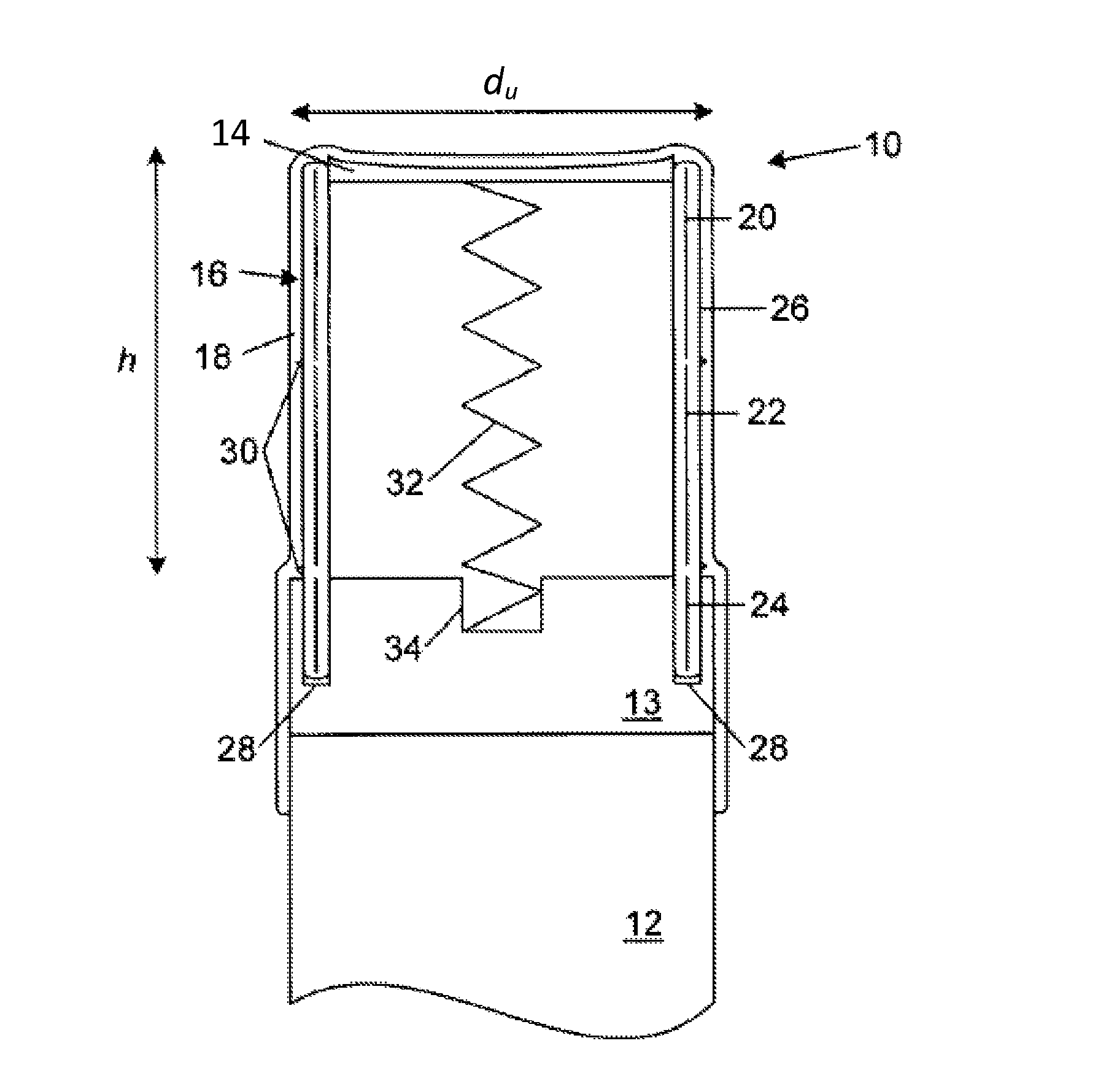
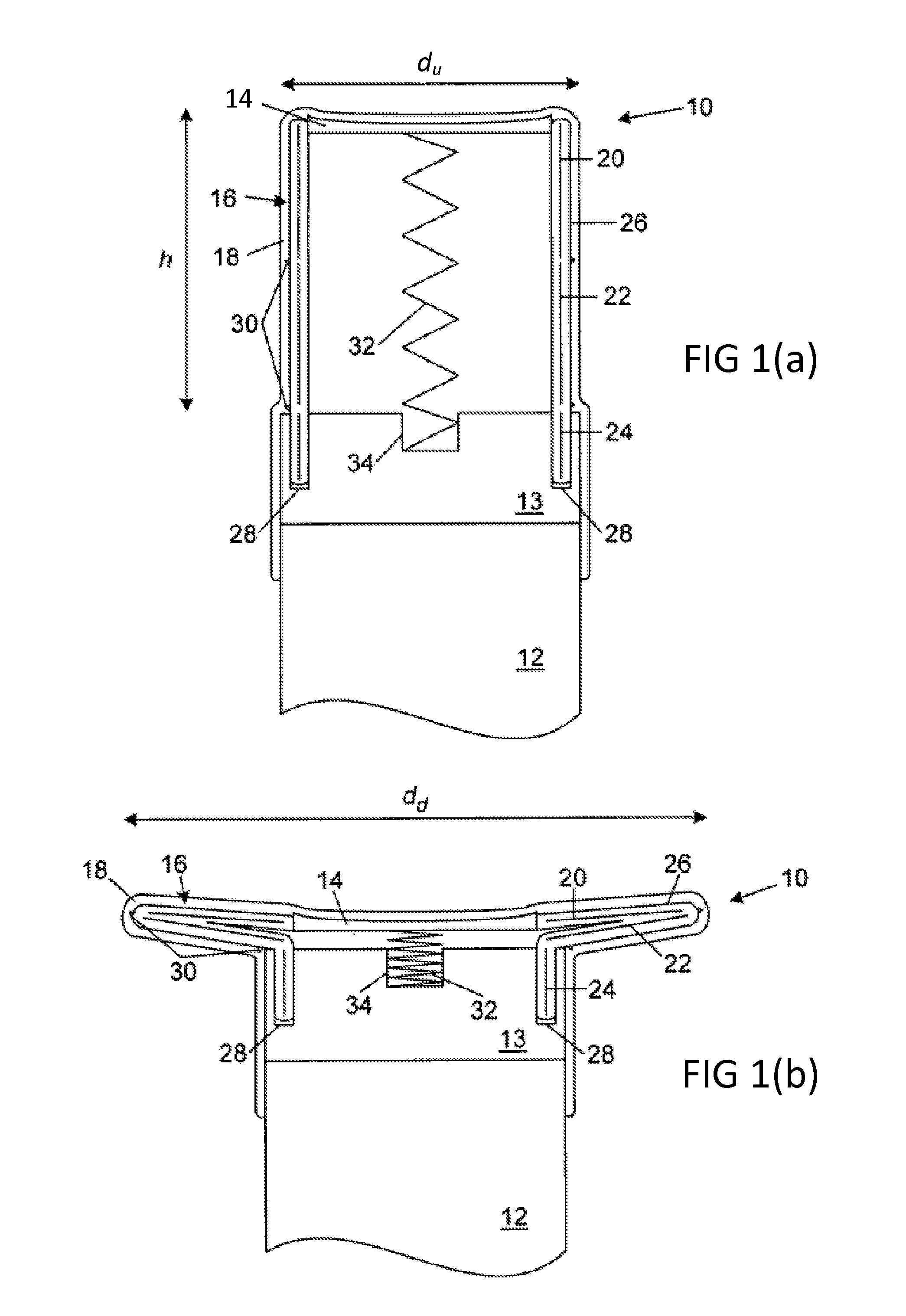
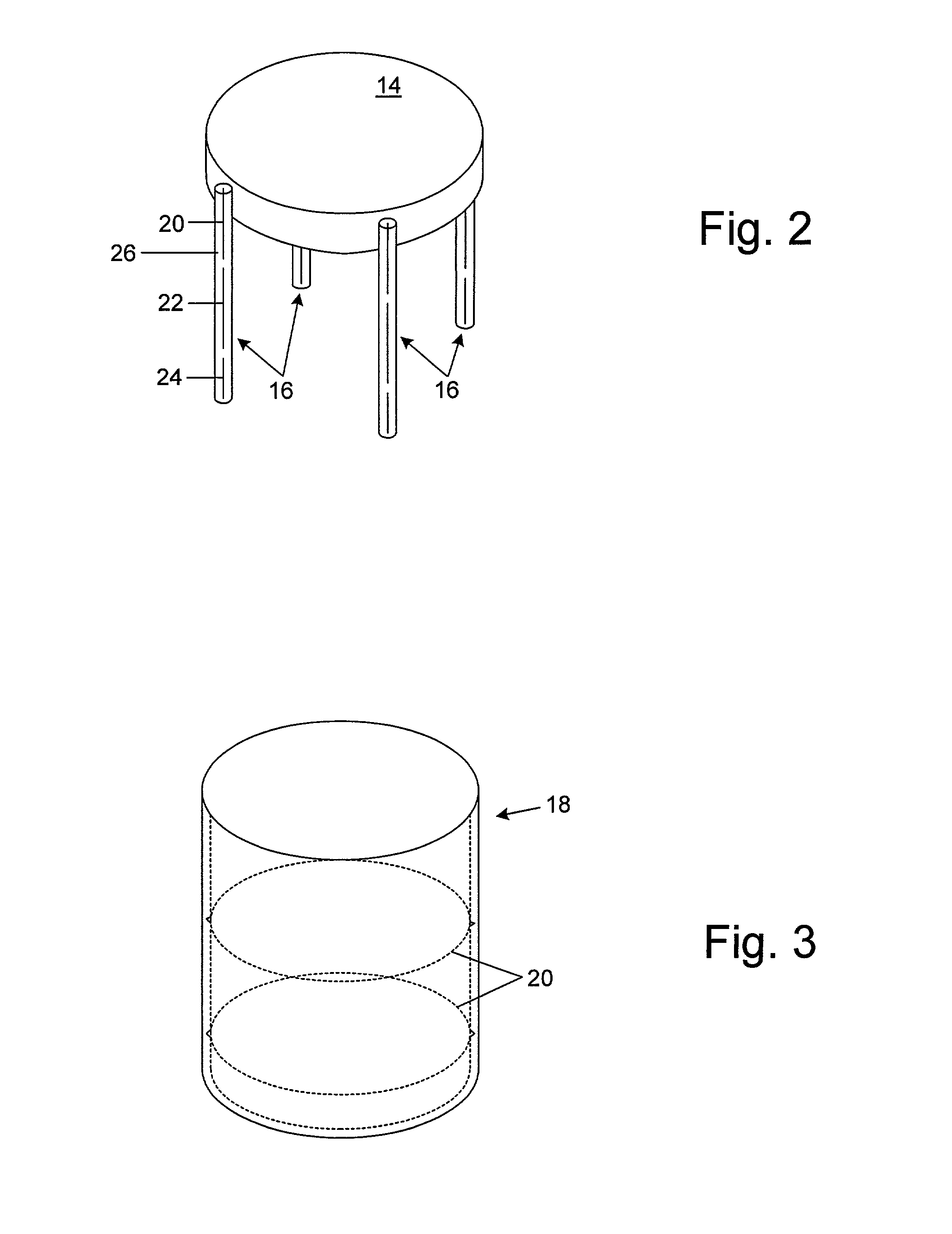
[0028]Turning now to the drawings, FIGS. 1(a) and (b) show cross-sectional side-view schematics of a deformable cap for a miniature joystick-type pointing device according to a FIG. 1(a) shows cap 10 in the undeformed state while FIG. 1(b) shows cap 10 in the deformed state. Cap 10 is placed on control stick 12 of a computer pointing device. Cap 10 includes bottom support 13, disc 14, wire supports 16, and elastic cover 18. Bottom support 13 is positioned on top of an upper surface of control stick 12. Bottom support 13 may be made of a rigid material such as hard plastic. An upper surface of disc 14 may be flat or, preferably, concave. A concave upper surface beneficially assists in increasing the surface area of contact between the cap and a operator's convex fingertip. Disc 14 may be made of a rigid material such as hard plastic. Each wire support 16 includes wires 20, 22, and 24 encased in flexible sleeve 26. Although three wires are shown for each wire support 16, less than or...

third embodiment

[0036]FIGS. 5(a) and (b) show cross-sectional side-view schematics of a deformable cap for a miniature joystick-type pointing device according to a FIG. 5(a) shows cap 50 in the undeformed state while FIG. 5(b) shows cap 50 in the deformed state. Portions of cap 50 identical to cap 10 of FIGS. 1(a) and (b) are labeled identically. Cap 50 is placed on control stick 12 of a computer pointing device. Cap 50 includes bottom support 53 and elastic cover 18. Bottom support 53 is positioned on top of an upper surface of control stick 12. Bottom support 53 may be made of a rigid material such as hard plastic. Cover 18 overlays bottom support 53 and an upper portion of control stick 12. Cover 18 may be made from either plastic or rubber. Cover 18 is cylindrical in shape and the end of cover 18 fitted over control stick 12 is opened. A perspective view of cover 18 is depicted in FIG. 3. The outer surface of cover 18 may be made smooth. Scores 30 may be located on the inner surface of cover 1...


PUM


Abstract

A deformable cap for a computer pointing device is provided that may be particularly useful for miniature joystick-type pointing devices such as the TrackPoin™ and ScrollPoint™ devices manufactured by the IBM corporation of Armonk, N.Y. When an operator places a fingertip on the cap, the cap deforms thereby advantageously increasing the surface area of contact between the cap and the fingertip. All embodiments of the cap are placed on an upper portion of a control stick of the pointing device. A first embodiment of the cap includes a bottom support, a disc, a plurality of wire supports, and an elastic cover that overlays the disc and wire supports. An inner surface of the cover may be scored to ensure repeatable deformation of the cap. A spring may be attached to a lower surface of the disc to assist the cap in regaining its original shape once the operator's fingertip is removed. A second embodiment of the cap includes a bottom support, a plurality of wire supports, and an elastic cover overlaying the wire supports. An inner surface of the cover may be scored. The cap may be hollow or may be filled with a deformable material. A third embodiment of the cap includes a bottom support and an elastic cover in which an inner surface of the cover may be scored. The cap may be hollow or may be filled with a deformable material.

Description

BACKGROUND OF THE INVENTION[0001]1. Field of the Invention[0002]This invention relates to computer input devices and, more particularly, to a deformable cap for a computer pointing device.[0003]2. Description of the Relevant Art[0004]Modern computer systems that implement graphical user interfaces (“GUIs”) typically include one or more pointing devices for the computer operator. Pointing devices typically allow an operator to move a cursor about the computer screen and to select objects. A commonly used pointing device is the computer mouse. Operation of the computer mouse typically requires a relatively large flat space. A variety of other pointing devices have been developed in an attempt to reduce the area occupied by the pointing device or required for use by the pointing device. A pervasive trend with notebook-style portable computers (also referred to as laptop computers) is attempting to reduce the size of every component of the computer while maintaining ease of use for the ...

Claims


Application Information

Patent Timeline
IPC IPC(8): H01H13/04
CPCG06F3/0338
Inventor HSU, PETER Y.HSU, JIMMY MING-DER
Owner IBM CORP
Why Eureka
Try Eureka