
Semiconductor device and method of manufacturing the same

a technology of semiconductor substrates and semiconductor devices, which is applied in the direction of semiconductor devices, electrical devices, capacitors, etc., can solve the problems of reducing the refresh time of semiconductor substrates, reducing the available area of inner spacers, and increasing the depth and/or width of inner spacers, so as to prevent gidl and improve the refresh time of transistors

Inactive Publication Date: 2011-10-11
SAMSUNG ELECTRONICS CO LTD
View PDF5 Cites 0 Cited by
  • Summary
  • Abstract
  • Description
  • Claims
  • Application Information

AI Technical Summary

Benefits of technology

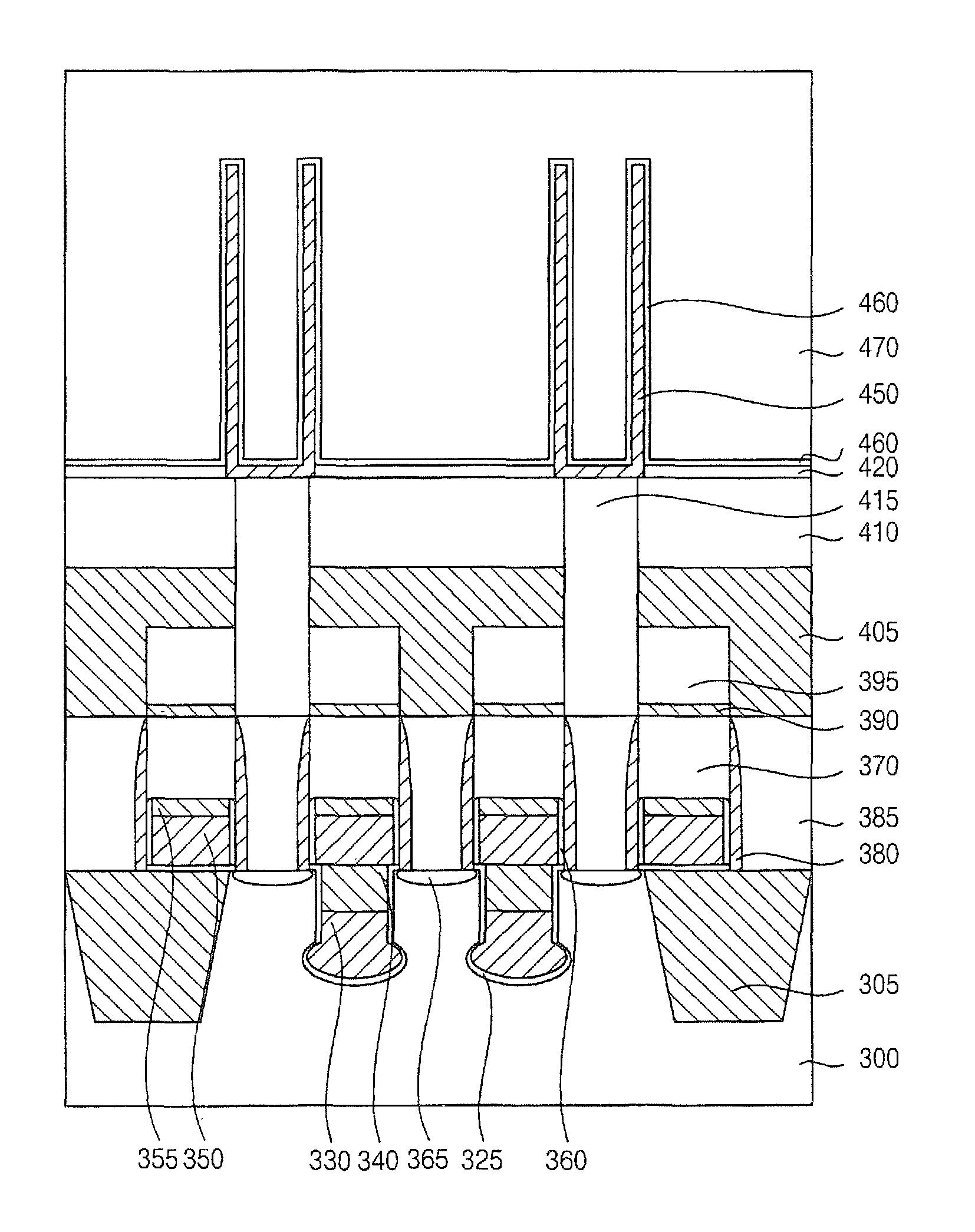
[0027]According to some example embodiments of the present inventive step, the source and drain regions may make contact with an inner spacer in the recessed portion of the substrate like a bridge in the RCAT / SRCAT structure, to thereby sufficiently prevent GIDL at the gate electrode and improve the refresh time of the transistor in spite of the downsizing of a minimum feature size of a semiconductor device.

Problems solved by technology

Accordingly, leakage currents may increase due to short channel effects and large amounts of dopants being implanted into semiconductor substrates, which may reduce the refresh times of the semiconductor substrates.
However, the above cell area reduction caused by the increase of integration degree may also reduce an available area for the inner spacer.
The inner spacer for reducing the GIDL may be difficult to form on the inner sidewall of the channel trench, which may affect the GIDL in the conventional RCAT structure as the cell area is reduced.
However, the increase of integration degree and the downsizing of the minimum feature size of a semiconductor device, for example, below about 4F2 (F: minimum feature size), may place various limitations on how much the depth and / or the width of the inner spacer can be increased, and thus the GIDL may be increased in the conventional RCAT structure as the cell area is reduced.
Accordingly, the RCAT structure may be inappropriate for some semiconductor devices despite the various advantages of the conventional RCAT structure.
In some cases, the RCAT structure may be completely replaced by a vertical pillar transistor (VPT) structure, and thus an RCAT structure may not be used in some semiconductor devices where the GIDL may not be sufficiently reduced.

Method used


Image

  • Semiconductor device and method of manufacturing the same
  • Semiconductor device and method of manufacturing the same
  • Semiconductor device and method of manufacturing the same

Examples


Embodiment Construction

[0034]Various example embodiments will be described more fully hereinafter with reference to the accompanying drawings, in which some example embodiments are shown. The present invention may, however, be embodied in many different forms and should not be construed as limited to the example embodiments set forth herein. Rather, these example embodiments are provided so that this disclosure will be thorough and complete, and will fully convey the scope of the present invention to those skilled in the art. In the drawings, the sizes and relative sizes of layers and regions may be exaggerated for clarity.

[0035]It will be understood that when an element or layer is referred to as being “on,”“connected to” or “coupled to” another element or layer, it can be directly on, connected or coupled to the other element or layer or intervening elements or layers may be present. In contrast, when an element is referred to as being “directly on,”“directly connected to” or “directly coupled to” anoth...


PUM


Abstract

In a semiconductor device and a method of manufacturing the same, a substrate is defined into active and non-active regions by a device isolation layer and a recessed portion is formed on the active region. A gate electrode includes a gate insulation layer on an inner sidewall and a bottom of the recessed portion, a lower electrode on the gate insulation layer and an inner spacer on the lower electrode in the recessed portion, and an upper electrode that is positioned on the inner spacer and connected to the lower electrode. Source and drain impurity regions are formed at surface portions of the active region of the substrate adjacent to the upper electrode. Accordingly, the source and drain impurity regions are electrically insulated by the inner spacer in the recessed portion of the substrate like a bridge, to thereby sufficiently prevent gate-induced drain leakage (GIDL) at the gate electrode.

Description

CROSS-REFERENCE TO RELATED APPLICATIONS[0001]This application claims the benefit of Korean Patent Application No. 10-2008-0072245, filed on Jul. 24, 2008, in the Korean Intellectual Property Office, the disclosure of which is incorporated herein in its entirety by reference.BACKGROUND[0002]1. Field[0003]Example embodiments relate to a semiconductor device and a method of manufacturing the same, and more particularly, to a semiconductor device including a recess channel array transistor (RCAT) structure, in which a gate electrode includes a bridge-shaped inner spacer, and a method of manufacturing the same.[0004]2. Description of the Related Art[0005]As semiconductor memory devices are becoming more highly integrated, unit cell areas, line widths and intervals of patterns, and channel lengths are being reduced. Accordingly, leakage currents may increase due to short channel effects and large amounts of dopants being implanted into semiconductor substrates, which may reduce the refres...

Claims


Application Information

Patent Timeline
Patent Type & Authority Patents(United States)
IPC IPC(8): H01L29/76H01L21/336
CPCH01L27/10814H01L27/10817H01L28/91H01L27/10852H01L27/10876H01L28/65H01L27/10823H01L21/823437H10B12/315H10B12/318H10B12/34H10B12/033H10B12/053H01L21/18
Inventor LEE, SUNG-SAMMOON, JOON-SEOKCHOI, YOUNG-JU
Owner SAMSUNG ELECTRONICS CO LTD
Learn More