Measuring system for detecting a rotary-linear displacement and corresponding rotary-linear drive

a technology of measuring system and rotary linear drive, which is applied in the direction of measuring devices, instruments, and using electrical means, can solve the problems that the measuring system cannot meet the requirements of certain injection molding machines, and achieve the effects of accurate control, saving axial construction space, and saving radial construction spa

Inactive Publication Date: 2011-10-11
SIEMENS AG
View PDF13 Cites 14 Cited by
  • Summary
  • Abstract
  • Description
  • Claims
  • Application Information

AI Technical Summary

Benefits of technology

Furthermore, the rotary sensor can be a hollow-shaft sensor in the interior of which the second measuring section is arranged. This type of construction has the advantage that the shaft can be pulled out of the machine backward, i.e. through the measuring system, especially in the case of injection molding machines.
If the decoupling device has a linear spherical liner and the rotary sensor is a hollow-shaft sensor, it is advantageous if the surface of the linear spherical liner forms the second measuring section. As a rule, this makes it possible to save axial construction space.
According to a further embodiment, a measuring shaft is permanently coupled to the shaft to be measured, on the one part of which measuring shaft the linear spherical liner runs and the other part of which comprises the first measuring section. As a result, the two sensors can be arranged axially behind one another so that it may be possible to save radial construction space.
It is particularly advantageous to use the measuring system described above for a rotary-linear drive wherein the signals of the linear sensor and of the rotary sensor are used for controlling the rotary-linear drive. This makes it possible to achieve very accurate control.

Problems solved by technology

In particular, this measuring system cannot meet the requirements of certain injection molding machines in which very accurate positioning capability is required.

Method used


Image

  • Measuring system for detecting a rotary-linear displacement and corresponding rotary-linear drive
  • Measuring system for detecting a rotary-linear displacement and corresponding rotary-linear drive
  • Measuring system for detecting a rotary-linear displacement and corresponding rotary-linear drive

Examples


Embodiment Construction

The exemplary embodiments described in greater detail in the text which follows represent preferred embodiments of the present invention.

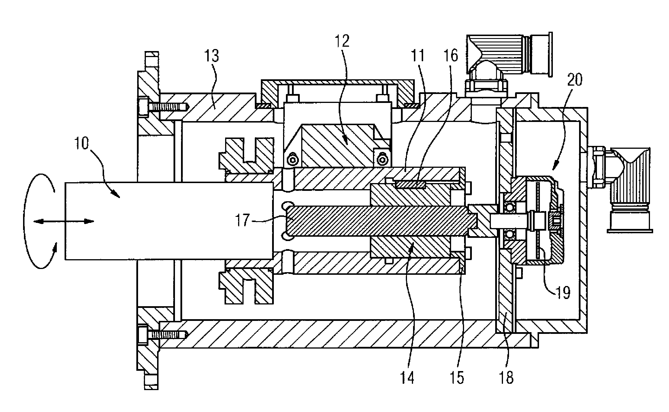
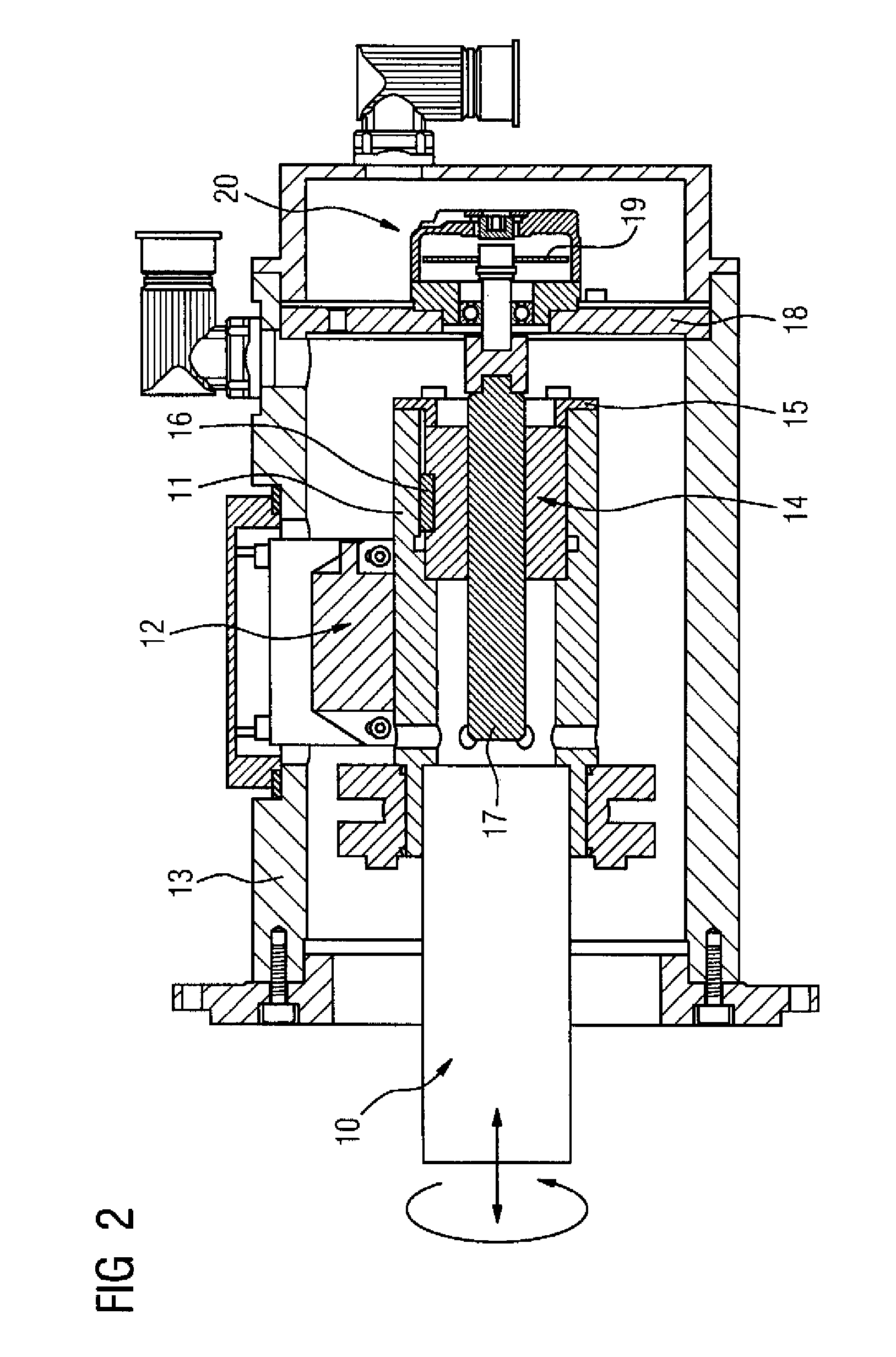
FIG. 2 shows a measuring system which can measure or detect the rotary-linear displacement of a shaft 10. The shaft 10 is, for example, a part of a drive of an injection molding machine. A sleeve 11 which performs the same rotary-linear displacement of the shaft 10 is coupled to the front end of the shaft 10. Annular grooves (in this case the first measuring section), which are not shown in FIG. 2, are milled into the sleeve 11. The annular grooves of the sleeve 11, or their displacement, respectively, are detected by a rotationally invariant rotary sensor 12. The latter is mounted on the housing 13 of the measuring system. Since the annular grooves surround the jacket of the sleeve 11 in the circumferential direction, the measurement signal of the linear sensor 12 is independent of the rotation of the sleeve 11 and thus of the shaft 10.

In the inte...


PUM

PropertyMeasurementUnit
rotary-linear displacementaaaaaaaaaa
rotary displacementaaaaaaaaaa
displacementsaaaaaaaaaa

Abstract

The invention relates to more accurate rotative and linear positional measurement for a rotary-linear drive. A measuring system comprising a linear sensor (12) and a rotary sensor (20) is disclosed. A decoupling unit (11,14,17) decouples the rotary displacement from the linear displacement of a shaft (10). The decoupling unit (11,14,17) has either a first measuring section (11), which is coupled in a fixed manner to the shaft to be measured (10) and tapped by the linear sensor (12) and a second measuring section (17), which is exclusively non-rotatably coupled to the shaft to be measured (10) and is tapped by the rotary sensor (20), or a first measuring section, which is coupled in a fixed manner exclusively linearly to the shaft to be measured and is tapped by the linear sensor and a second measuring section, which is non-rotatably coupled to the shaft to be measured and is tapped by the rotary sensor. In each case, the linear displacement is decoupled from the rotary displacement for the measuring process, permitting high-resolution standard measuring sensors to be used.

Description

BACKGROUND OF THE INVENTIONThe present invention relates to a measuring system for detecting a rotary-linear displacement of a shaft comprising a linear sensor and a rotary sensor. In particular, the present invention relates to a rotary-linear drive which is equipped with such a measuring system.A drive, particularly an injector and metering unit in a plastic injection molding machine or similar machine applications requires the implementation of a rotary displacement and a linear displacement on the drive shaft. It must be possible to generate these displacements independently of one another, on the one hand, but also superimposed. Control of the combined drive requires implementation of a rotary and linear positional measurement with the aid of a measuring system.Hitherto, rotary-linear drives were available which have, for example, the structure reproduced in FIG. 1. The drive consists of a rotary drive 1 and a linear drive 2 which are arranged axially behind one another and lin...

Claims


Application Information

Patent Timeline
Patent Type & Authority Patents(United States)
IPC IPC(8): G01B7/14
CPCB29C45/5008B29C45/76B29C2945/76113B29C2945/7612B29C2945/76187G01D5/24433G01D2205/24G01D2205/18
Inventor BUDDE, THOMASINALKAC, AZIZTOLDONOV, MYKHAYLOVOLLMER, ROLF
Owner SIEMENS AG
Why Eureka
Try Eureka