Objective lens and optical data storage apparatus comprising the objective lens

a technology of optical data storage and objective lens, which is applied in the field of objective lens, can solve the problems of inconvenient use, inconvenient operation, and inability to meet the needs of data recording,

Inactive Publication Date: 2011-10-11
THOMSON LICENSING SA
View PDF8 Cites 2 Cited by
  • Summary
  • Abstract
  • Description
  • Claims
  • Application Information

AI Technical Summary

Benefits of technology

[0007]It is thus an object of the present invention to provide an objective lens for a compatible drive, which is applicable both in the near-field optical regime and in the far-field optical regime.
[0010]With this object in view, an objective lens is provided that is switchable between a far-field mode and a near-field mode. The objective lens comprises a lens, an optical element having a variable refractive index and a solid immersion lens. The aforementioned elements are disposed on a common optical axis. The optical element having a variable refractive index is arranged at a convex side of the solid immersion lens and has a top and a bottom surface arranged adjacent to each other in the direction of the optical axis. The bottom surface of said optical element has a concave shape that is adapted to the shape of the convex side of the solid immersion lens. The curvature of the top surface of said optical element is lower than the curvature of the convex side of the solid immersion lens. The refractive index of said optical element is varies in such way that a difference between the refractive index of said optical element and the solid immersion lens is small in the far-field mode so that the solid immersion lens and the optical element act substantially as a single optical element in the far-field mode, whereas said difference is large in the near-field mode so that the optical effect of the solid immersion lens is significant in the near-field mode.
[0012]Typically, a solid immersion lens is a plano-convex optical structure. Its optical effect is due to a very small working distance, which allows evanescent waves to propagate into the solid immersion lens, in combination with a high curvature of its convex side. Consequently, by arranging a further optical element with a variable refractive index at the convex side of the solid immersion lens, the refraction of said solid immersion lens may be varied. Preferably, said further optical element has a concave surface that is adapted to the convex shape of the solid immersion lens and further an opposite surface that is lower in curvature than the convex side of the solid immersion lens. In order to make this optical element switchable, it is made out of a material with a switchable refractive index.
[0013]The main idea for switching the objective lens between a far-field mode and a near-field mode is the variable difference between the refractive indices of said optical element and the solid immersion lens. In case the difference between the refractive indices is high, the optical effect of the solid immersion lens is significant, as it is known from the use of solid immersion lenses in air. In case the difference of the optical indices is small, the optical effect of the solid immersion lens is significantly lower, because the solid immersion lens plus the optical element act more or less as a single optical element. Since the surface of the optical element disposed opposite the solid immersion lens has a lower curvature than the convex side of the solid immersion lens, the overall optical effect is significantly lower than the one of the solid immersion lens. The objective lens is applicable in the optical far-field regime as well as in the optical near-field regime. A further advantage is that the optical system is realized without any moving parts. Consequently, a simple and reliable objective lens is provided. This feature makes it a perfect choice for a compatible drive for an optical data storage apparatus.
[0015]Advantageously, the optical element is a liquid having a variable refractive index, which is confined in a cavity that is limited by a top and a bottom part in the direction of the optical axis. The top and bottom surfaces of the optical element are formed by a surface of the top and bottom part facing said cavity, respectively. Preferably, the top and bottom part each comprise an electrode, said electrodes being designed for generating an electric field inside the cavity for switching the refractive index of said liquid. Favorably a liquid crystal is used as said liquid. Accordingly, the refractive index of the optical element may be varied in a simple way. By applying an electric field to the liquid crystal material, the refractive index of said optical element is changed quickly and reliable.
[0022]Preferably, the refractive index of the optical element in the far-field mode as well as the refractive index of the solid immersion lens is approximately n=3. A refractive index of n=3 is a typical value known for material used for solid immersion lenses. Accordingly, it is advantageous if the optical element is capable of reaching this value. It is further advantageous if the refractive index of the optical element is approximately n=1 in case the objective lens is working in the near-field mode. A refractive index of n=1 provides nearly the same situation as in air. Consequently, the solid immersion lens shows its best efficiency.

Problems solved by technology

Nowadays information technology is confronted with an increasing amount of data, due to more complex or multimedia applications.
Optical data storage is generally limited by the optical resolution of the read / write-system.
Straightforward methods of increasing the optical resolution involve widening of the focused beam and opening angle, i.e. the numerical aperture NA, at the costs of lens complexity.
However, such optical heads are usually fragile and expensive.

Method used


Image

  • Objective lens and optical data storage apparatus comprising the objective lens
  • Objective lens and optical data storage apparatus comprising the objective lens
  • Objective lens and optical data storage apparatus comprising the objective lens

Examples


Embodiment Construction

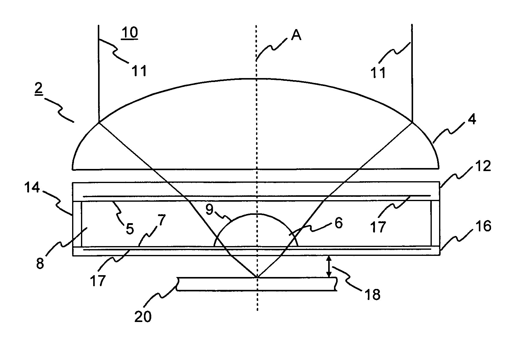
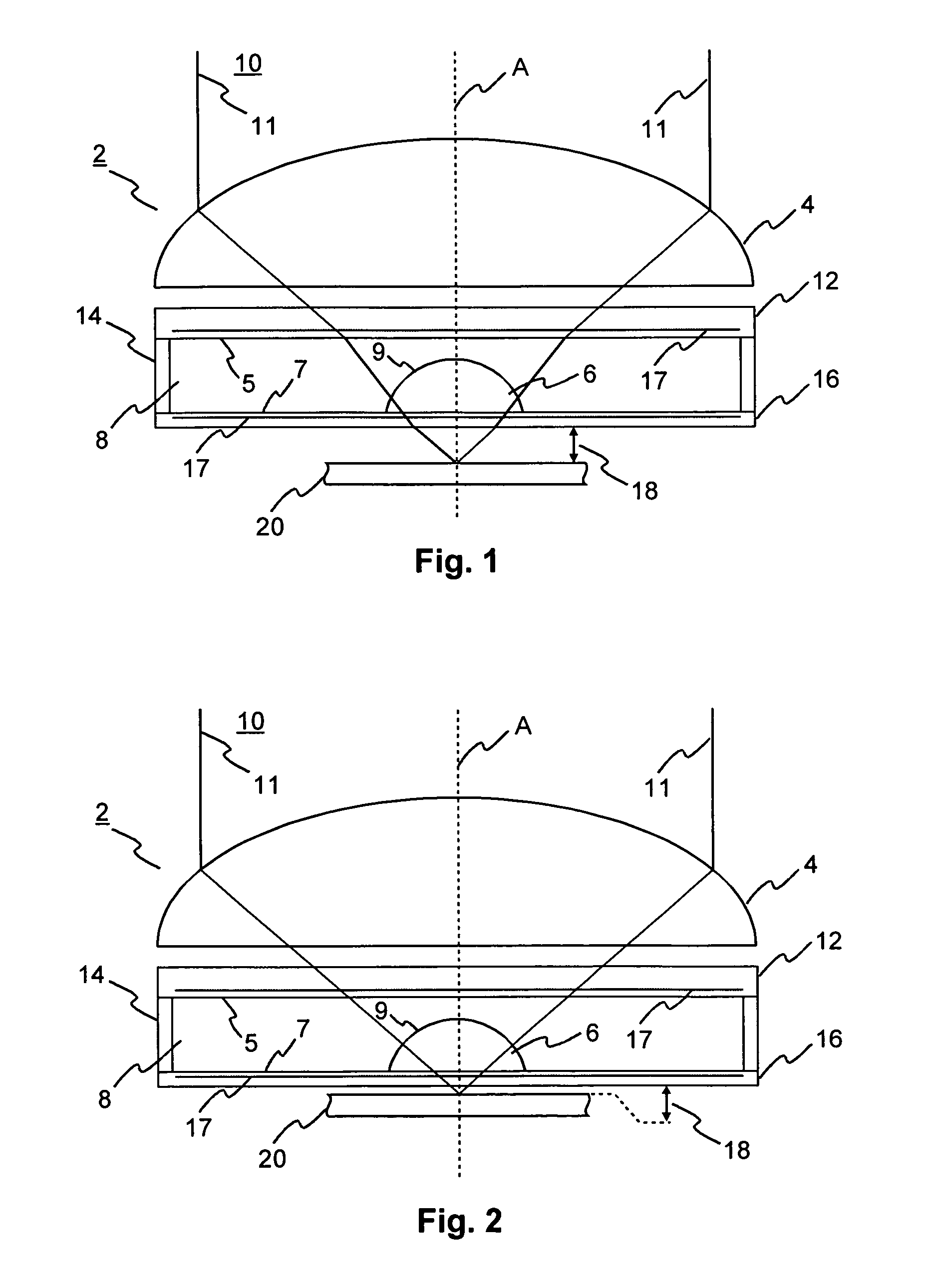
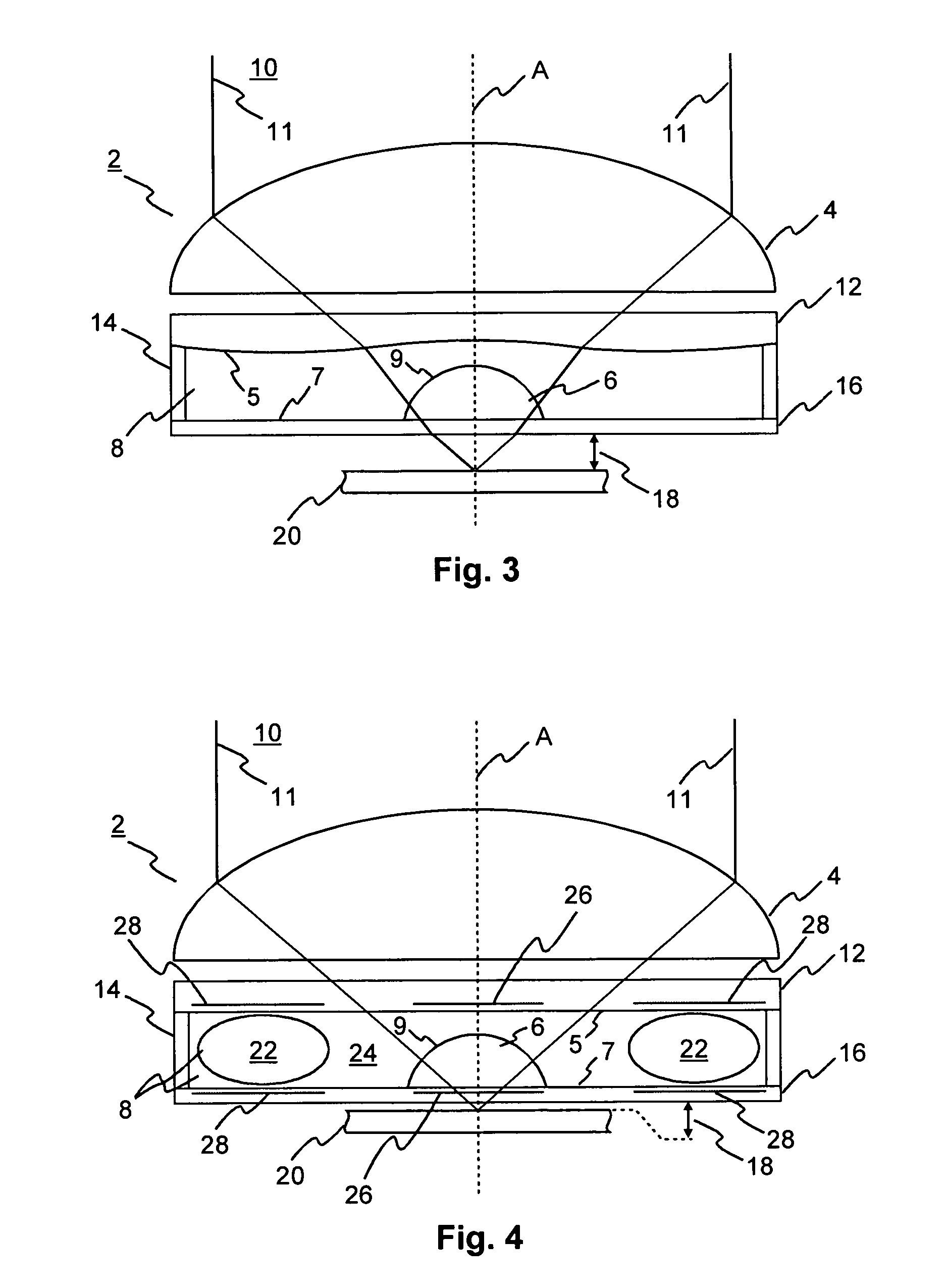
[0031]A first embodiment of an objective lens 2 according to the invention is shown in FIGS. 1 and 2, wherein FIG. 1 depicts the objective lens 2 in a far-field mode, whereas FIG. 2 depicts the objective lens 2 in a near-field mode. The objective lens 2 comprises a lens 4, a solid immersion lens 6 and an optical element 8 having a variable refractive index. The aforementioned units, i.e. the optical element 8, the lens 4 and the solid immersion lens 6 are disposed on a common optical axis A, drawn as a dashed line. According to the embodiment shown in FIGS. 1 and 2, the optical element 8 is a liquid crystal confined in a cavity that is limited by a top part 12 and a bottom part 16 spaced apart by an annular ring 14 in a direction of the optical axis A. The shape of the optical element 8 is determinate by a shape of a surface facing the cavity of the top and bottom part 12, 16, respectively. These interfaces between the liquid confined by the cavity and said inner surfaces determine ...


PUM

PropertyMeasurementUnit
refractive indexaaaaaaaaaa

Abstract

An objective lens is described, which is switchable between a far-field mode and a near-field mode. The objective lens comprises a lens, an optical element having a variable refractive index and a solid immersion lens, which are disposed on a common optical axis, wherein the optical element is arranged at a convex side of the solid immersion lens and has a top and a bottom surface arranged adjacent to each other in a direction of the optical axis, the bottom surface having a concave shape that is adapted to the shape of the convex side of the solid immersion lens and the top surface having a curvature that is lower than a curvature of the convex side of the solid immersion lens, and wherein a difference between a refractive index of the optical element and the solid immersion lens is small in the far-field mode so that the solid immersion lens and the optical element act substantially as a single optical element in the far-field mode, whereas the difference is large in the near-field mode so that the optical effect of the solid immersion lens is significant in the near-field mode.

Description

[0001]This application claims the benefit, under 35 U.S.C. §119 of European Patent Application 09305774.3, filed Aug. 21, 2009.FIELD OF THE INVENTION[0002]The present invention relates to an objective lens, which is switchable between a far-field mode and a near-field mode, and further to an apparatus for reading from and / or writing to optical recording media comprising an optical head with the aforementioned objective lens.BACKGROUND OF THE INVENTION[0003]Nowadays information technology is confronted with an increasing amount of data, due to more complex or multimedia applications. Accordingly, removable data storage devices with a high storage capacity are needed, e.g. for high resolution movies or video games. Well at the beginning of information technology, magnetic storage devices were favored, while nowadays, optical storage media such as CD (Compact Disk), DVD (Digital Versatile Disk) or BD (Blu-Ray Disk) are dominating the market for removable data storage media.[0004]Optica...

Claims


Application Information

Patent Timeline
Patent Type & Authority Patents(United States)
IPC IPC(8): G11B7/00G11B7/135
CPCG11B7/1369G11B7/1374G11B7/1387G11B2007/13727G11B2007/0006
Inventor KNITTEL, JOACHIM
Owner THOMSON LICENSING SA
Why Eureka
Try Eureka