

Structure for mounting electricity storage pack on vehicle
a technology for mounting structures and electricity storage packs, which is applied in the direction of electric propulsion mounting, cell components, cell component details, etc., can solve the problems of insufficient protection of electricity storage packs, the brokenness of electricity storage packs themselves, etc., and achieve the effect of suppressing damage to electricity storage packs
- Summary
- Abstract
- Description
- Claims
- Application Information
AI Technical Summary
Benefits of technology
Problems solved by technology
Method used
Image


Examples
embodiment 1
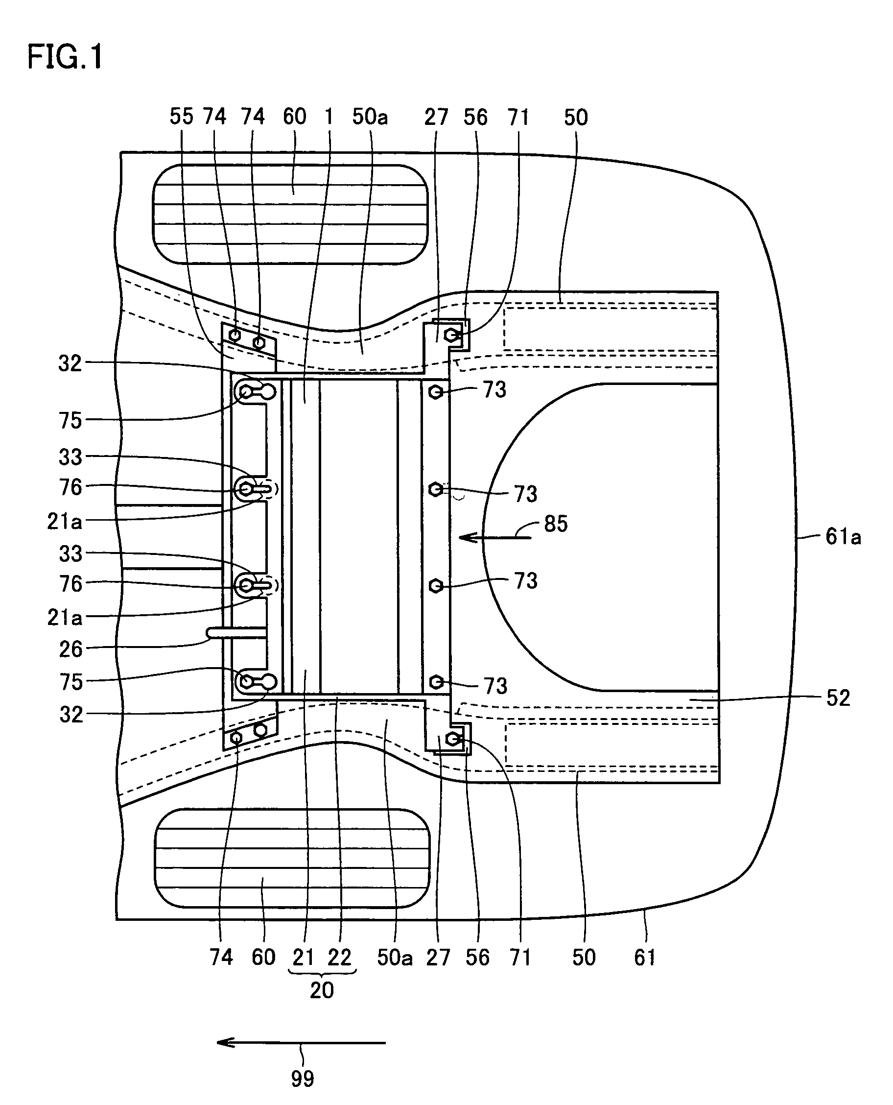
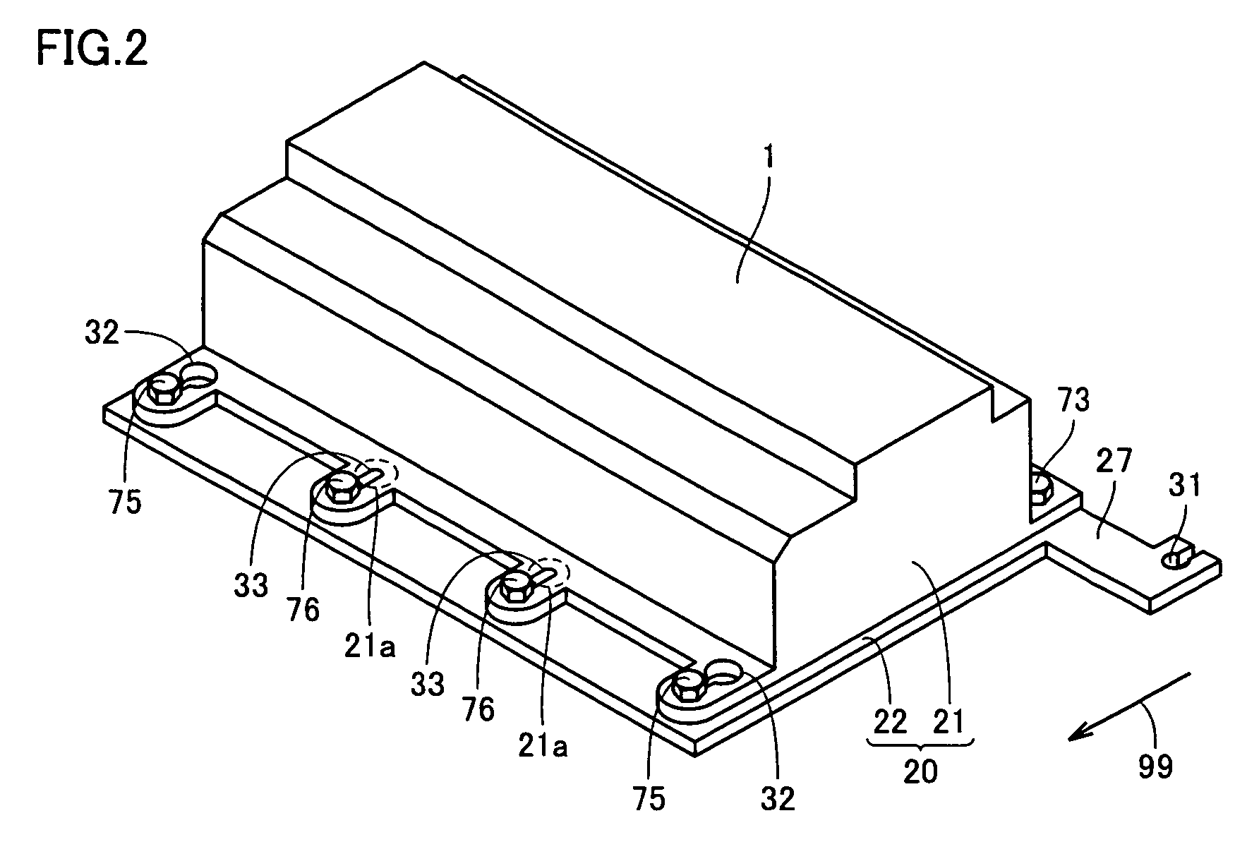
[0043]With reference to FIGS. 1 to 12, a structure for mounting an electricity storage pack on a vehicle in an embodiment 1 according to the present invention will be described. In the structure for mounting on the vehicle in the present embodiment, an impact relaxation means for detaching the electricity storage pack when an impact from an outside high position is applied on the electricity storage pack is formed at the electricity storage pack.
[0044]An electricity storage device such as a secondary battery and a capacitor is housed in a case and mounted on an automobile. In the present invention, a device including the case and the electricity storage device housed in the case is referred to as an electricity storage pack. The electricity storage pack may include other inner component parts. Other inner component parts include cooling devices such as a cooling duct and a cooling fan for cooling the electricity storage device and an electric device for converting electric power, fo...
embodiment 2
[0096]With reference to FIGS. 13, 14A, and 14B, a structure for mounting an electricity storage pack on a vehicle in an embodiment 2 according to the present invention will be described. The structure for mounting the electricity storage pack on the vehicle in the present embodiment is different from Embodiment 1 in structures of portions of a front end portion of the electricity storage pack to be fixed by screws.
[0097]FIG. 13 is a schematic perspective view of a front portion of the battery pack in the present embodiment. An arrow 99 indicates a forward direction of the vehicle body. The battery pack in the present embodiment includes a case 45. Case 45 has an upper case 46 and a lower case 47. Case 45 has recessed portions 45a at its front end portion. Recessed portions 45a are respectively formed at portions where bolts are to be disposed.
[0098]At a bottom portion of each recessed portion 45a, a step portion 45b is formed. Step portion 45b is formed to have a step-like sectional...
embodiment 3
[0106]With reference to FIGS. 15 to 17, a structure for mounting an electricity storage pack on a vehicle in an embodiment 3 and according to the present invention will be described. The structure for mounting the battery pack on the vehicle in the present embodiment is different from Embodiment 1 in the structure of the front portion of the battery pack.
[0107]FIG. 15 is a schematic sectional view of a portion of the battery pack in the present embodiment. At the front end portion of battery pack 1, screw holes 32 are formed on opposite sides in the width direction. By disposing bolts 75 in screw holes 32, the front end portion of battery pack 1 is fixed to mount 55 similarly to Embodiment 1.
[0108]Battery pack 1 in the present embodiment has bolts 77 as third screws at its front end portion. Bolts 77 are formed to fix upper case 21 and lower case 22 to each other. Bolts 77 are formed so as not to fix battery pack 1 and mount 55 to each other.
[0109]FIG. 16 is a schematic perspective ...
PUM
| Property | Measurement | Unit |
|---|---|---|
| impact force | aaaaa | aaaaa |
| brittle | aaaaa | aaaaa |
| strength | aaaaa | aaaaa |
Abstract
Description
Claims
Application Information