Transition device for optical waveguides

a technology of optical waveguides and transition devices, which is applied in the field of transition devices for optical waveguides, can solve the problems of small losses, strong limitation of the extension of the light mode in the waveguide,

Active Publication Date: 2011-10-18
II VI DELAWARE INC
View PDF5 Cites 14 Cited by
  • Summary
  • Abstract
  • Description
  • Claims
  • Application Information

AI Technical Summary

Problems solved by technology

High index contrast leads to a strong limitation of the extension of the light mode in the waveguide and vice versa.
It is often desirable to mix high index contrast waveguides with low index contrast waveguides in the same technical application, whereby the problem arises of achieving transition parts between such waveguides, which transitions parts would lead to small losses and not to other problems such as for instance unwanted reflections.

Method used


Image

  • Transition device for optical waveguides
  • Transition device for optical waveguides
  • Transition device for optical waveguides

Examples


Embodiment Construction

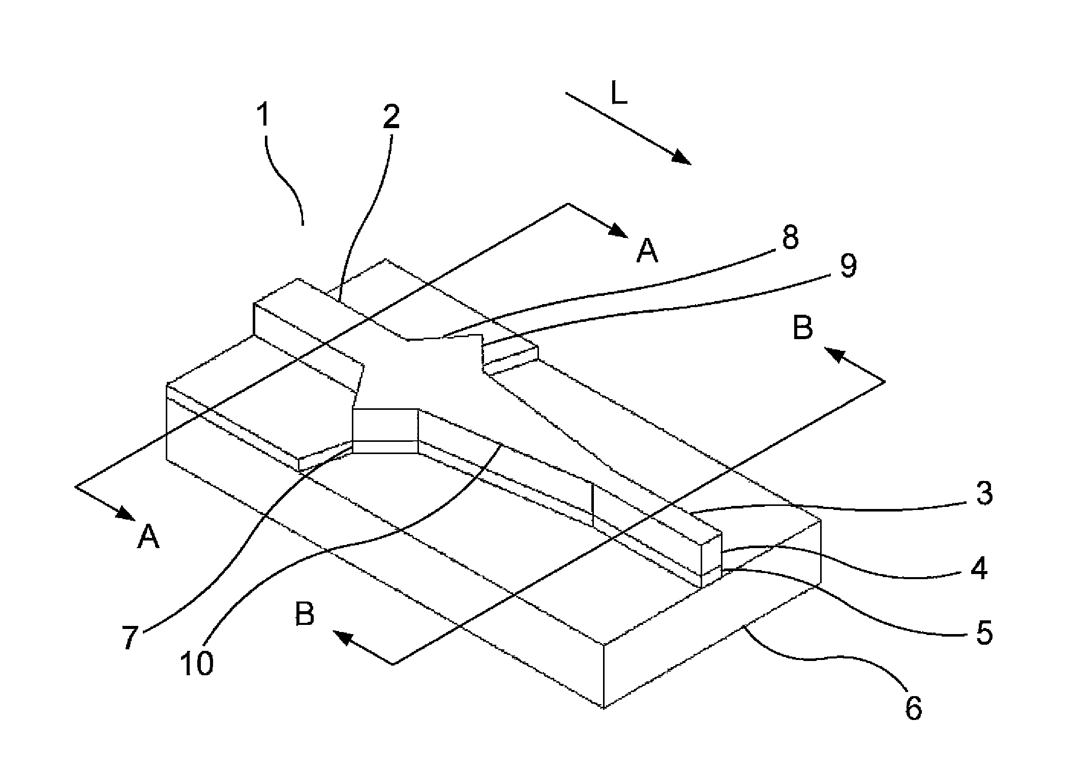
[0024]FIG. 1 is a perspective view over a transition part 1 according to a first preferred embodiment. The transition part 1 connects a first low index contrast waveguide 2 to a second high index contrast waveguide 3.

[0025]The transition part 1 has a longitudinal direction L, coincident with the main direction of propagation of the light being conveyed through the waveguides 2, 3.

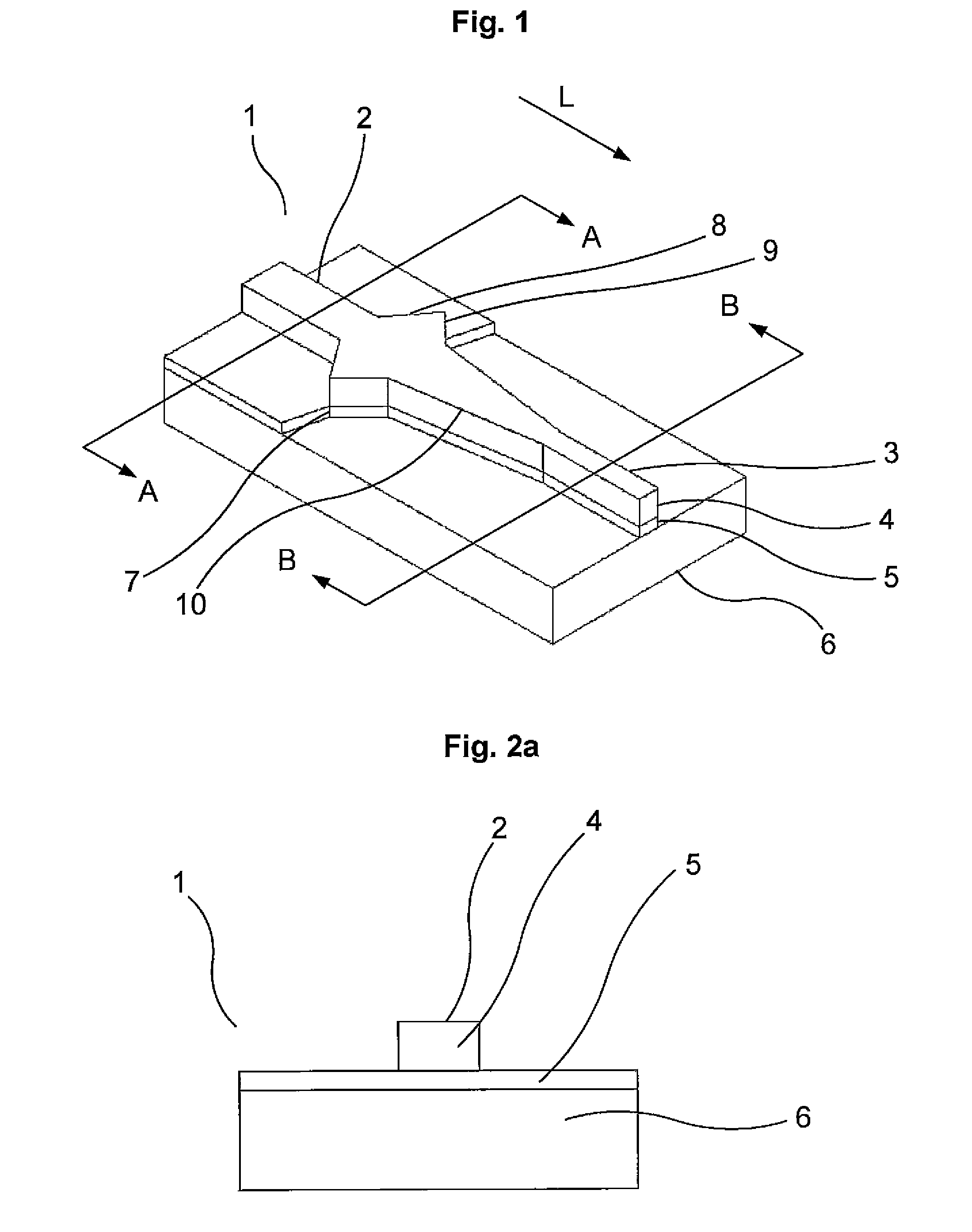
[0026]FIG. 2a shows a longitudinal cross section taken along the line A-A of FIG. 1, and thus illustrates the longitudinal cross sectional form of the first waveguide 2. A low index contrast waveguide may also be denoted as “weakly waveguiding”, which expression aims at the weaker uniting of the light travelling through the waveguide. Hence, the light mode has relatively large dimensions in the first waveguide 2.

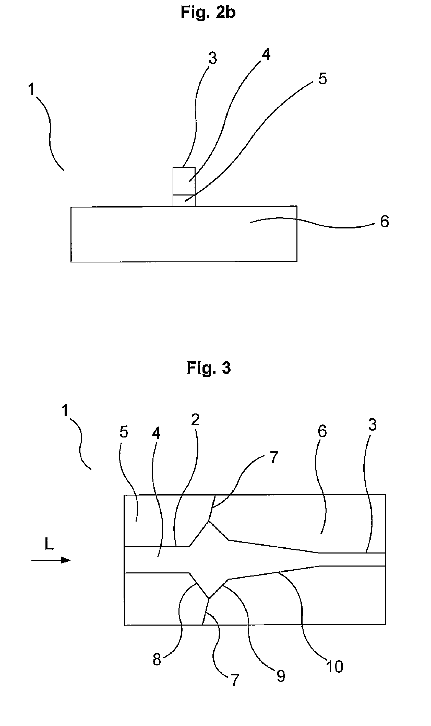
[0027]Correspondingly, a high index contrast waveguide may be denoted as “strongly waveguiding”. FIG. 2b shows a cross longitudinal section taken along the line B-B of FIG. 1, and therefore illustra...


PUM

PropertyMeasurementUnit
refractive indexaaaaaaaaaa

Abstract

A transition part (1) between two optical waveguides (2,3) with different index contrast is characterised in that the transition part (1) includes a non-adiabatically up-tapered longitudinal section (8), and in that the transition (7) between the two waveguides (2,3) is arranged after the up-tapered longitudinal section (8) as seen along the main direction (L) of propagation of the light. A method of manufacturing the transition part is also described.

Description

BACKGROUND OF THE INVENTION[0001]1. Field of the Invention[0002]The present invention relates to a transition part between two optical waveguides. More precisely, the invention relates to a transition part between two such waveguides with different index contrast.[0003]2. Description of the Related Art[0004]For example, optical waveguides are used within the field of optical communications. The ability of a waveguide to limit the size of the light field perpendicularly to the longitudinal direction of the waveguide depends on its index contrast. Herein, the expression index contrast refers to a measure of the difference in effective index in a lateral direction, diametrically to the main direction of propagation of the light, for the effective index profile of the waveguide when reduced to one dimension. High index contrast leads to a strong limitation of the extension of the light mode in the waveguide and vice versa.[0005]For example, low index contrast waveguides are used in so c...

Claims


Application Information

Patent Timeline
Patent Type & Authority Patents(United States)
IPC IPC(8): G02B6/26
CPCB82Y20/00G02B6/1228G02B6/1223Y10T29/49016
Inventor GRANESTRAND, PERWESSTROM, JAN-OLOFADAMS, DAVE
Owner II VI DELAWARE INC
Why Eureka
Try Eureka