
Sheet feeding device and image reading device

a feeding device and image technology, applied in the field of sheet feeding device and image reading device, can solve the problems of limiting a number of document sheets and the load that acts on the document sheets, and achieve the effect of reducing the load to be applied

Inactive Publication Date: 2011-10-18
BROTHER KOGYO KK
View PDF27 Cites 15 Cited by
  • Summary
  • Abstract
  • Description
  • Claims
  • Application Information

AI Technical Summary

Benefits of technology

[0009]In the ADF that employs the above-described sheet-feed system, the document sheets which are successively discharged to the sheet-receiving tray receive a load from the document sheets which are already stacked on the sheet-receiving tray after having been discharged. Where the weight of the document sheets stacked on the sheet-receiving tray increases with an increase in the number of the discharged and stacked sheets, for instance, friction resistance that is received by the document sheets to be subsequently discharged thereafter inevitably increases. Further, where the document sheets stacked on the sheet-receiving tray are warped in the sheet-feed direction, namely, where the discharged document sheets stacked on the sheet-receiving tray droop downwardly, the document sheets to be subsequently discharged receive a load at leading end portions thereof due to a contact with the drooped document sheets. In particular when the length of the sheet-receiving tray as measured in the sheet-feed direction is made small in an attempt to enhance the usability and the viewability of the sheet-supplying tray, the load due to the warpage or drooping of the document sheets is outstandingly increased.
[0010]The load that acts on the document sheets as described above inevitably limits a number of the document sheets that can be discharged by the ADF successively and smoothly to the sheet-receiving tray. However, it is desirable that a number of the document sheets that can be fed successively by the ADF be as large as possible. Moreover, it is desirable that the document sheets be discharged to the sheet-receiving stay with high stability, without a risk of falling off from the sheet-receiving tray and a risk of being bent.
[0011]It is therefore a first object of the invention to provide a sheet feeding device which is configured such that each of document sheets to be successively discharged to a sheet-receiving tray smoothly slides under document sheets that have been already discharged to and stacked on the sheet-receiving tray, thereby ensuring smooth discharging of the document sheets. It is a second object of the invention to provide an image reading device that comprises such a sheet feeding device.
[0015]Because the sheets which have been discharged to the second tray are warped as described above, a sheet to be subsequently discharged can smoothly slide under the sheets which have been already discharged to and stacked on the second tray. Further, the thus warped sheets on the second tray are prevented from drooping downward at leading end portions thereof that protrude from the second tray, thereby reducing a load to be applied to the feeding of the sheets that are to be discharged thereafter. Accordingly, the plurality of sheets can be smoothly discharged to the second tray, whereby the number of sheets that can be successively fed by the present sheet feeding device can be increased.

Problems solved by technology

The load that acts on the document sheets as described above inevitably limits a number of the document sheets that can be discharged by the ADF successively and smoothly to the sheet-receiving tray.

Method used


Image

  • Sheet feeding device and image reading device
  • Sheet feeding device and image reading device
  • Sheet feeding device and image reading device

Examples


first embodiment

1. Outline of Image Reading Device

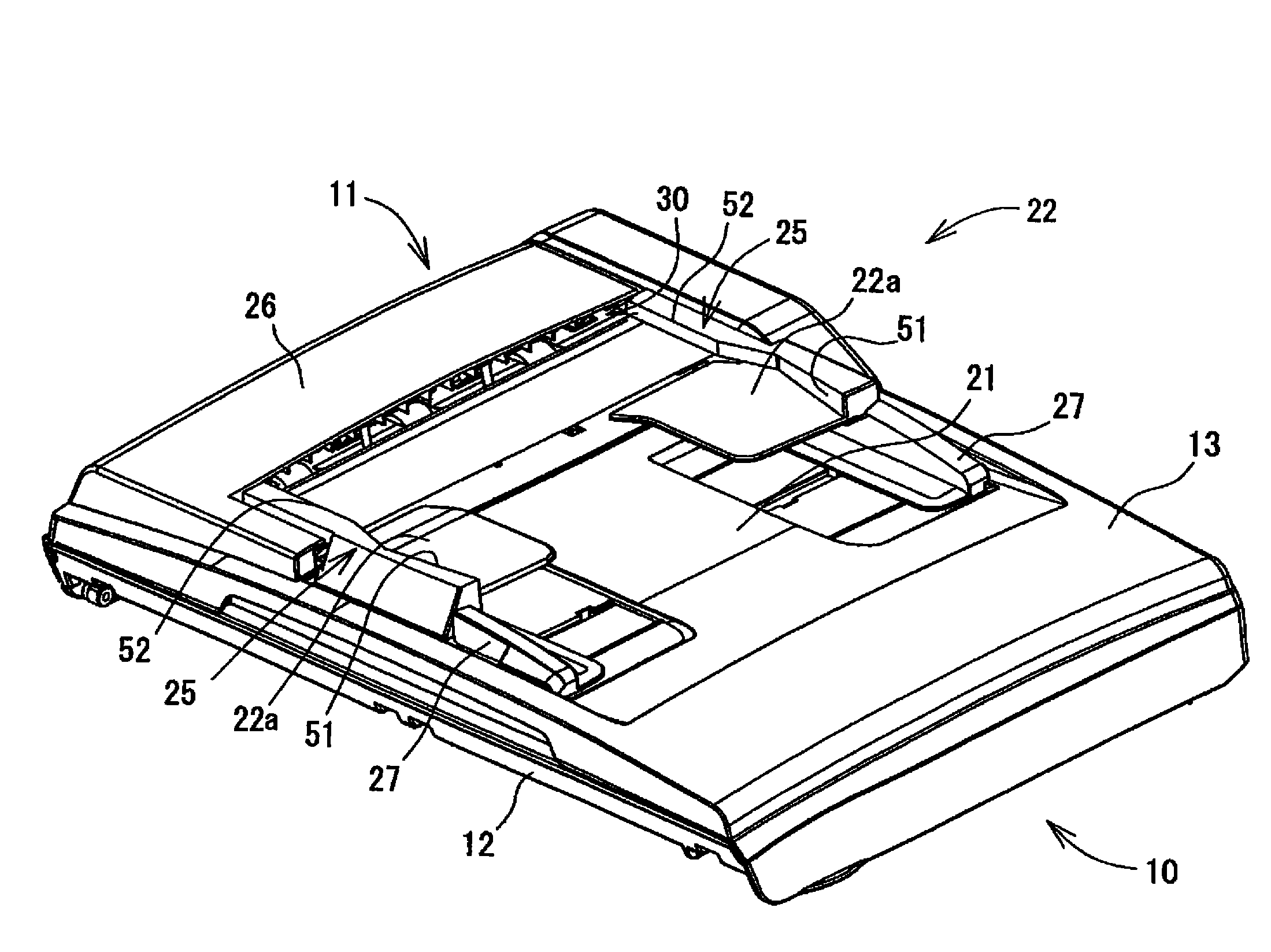
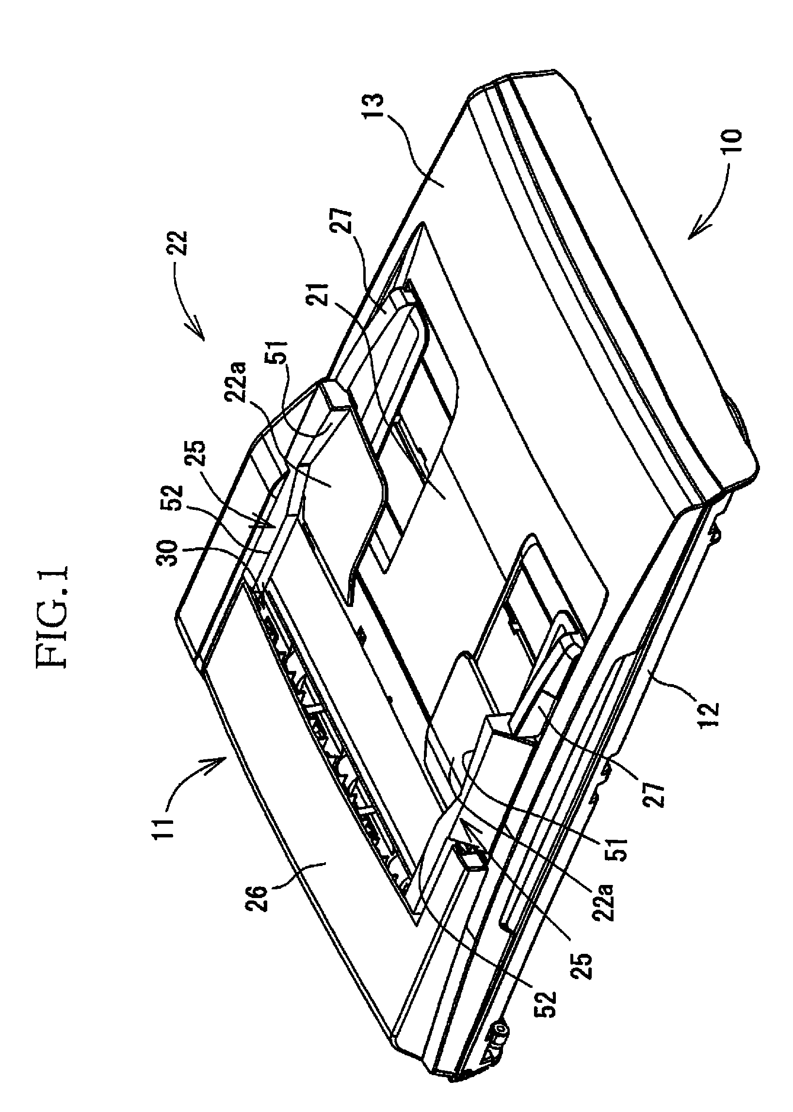
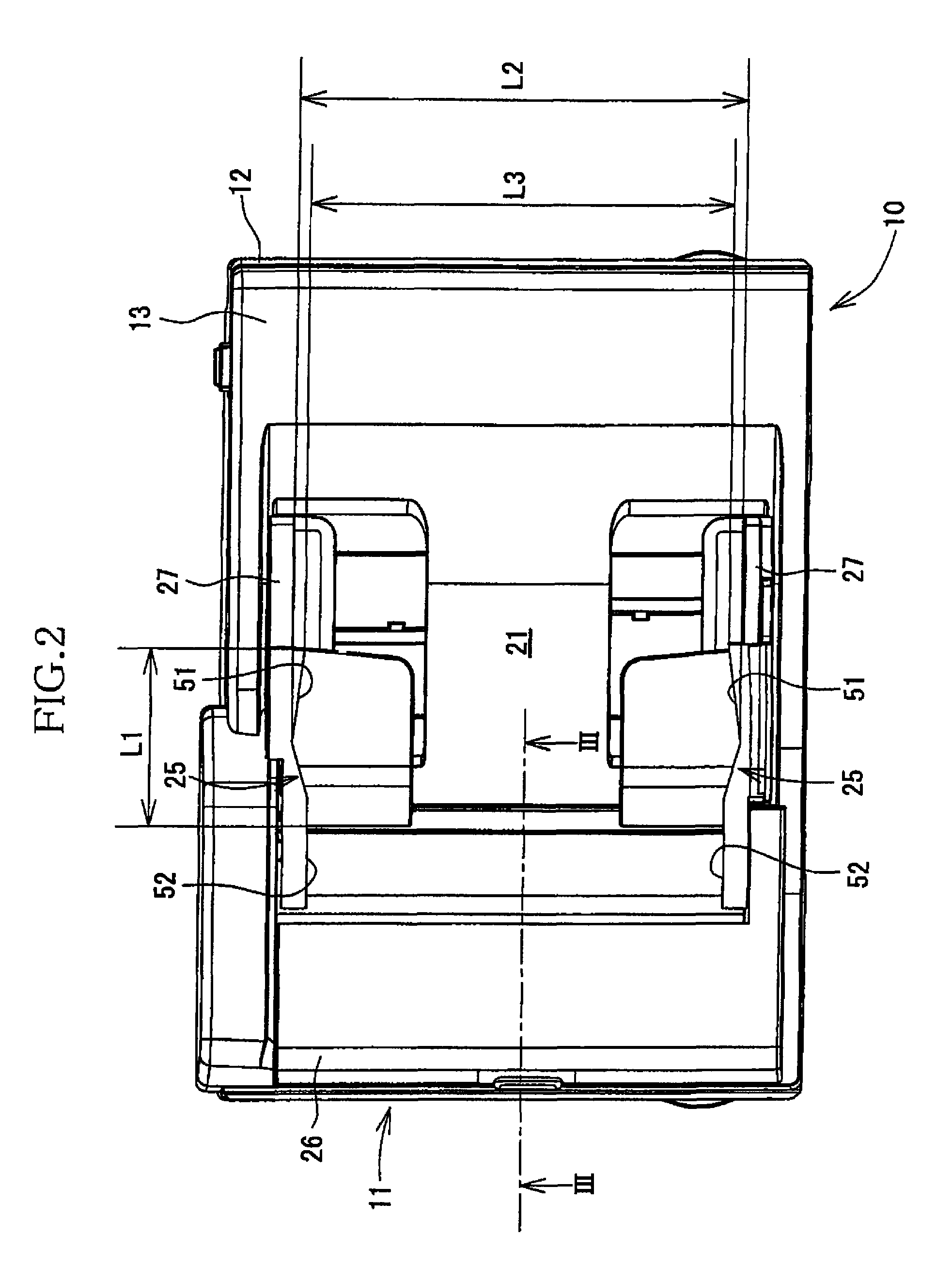
[0029]Referring first to FIGS. 1-3, there will be explained an image reading device according to a first embodiment of the invention. The image reading device indicated at 10 is a flat bed scanner (FBS) equipped with an auto document feeder (ADF) 11. The sheet feeding device according to the present invention is embodied as the ADF 11. While the image reading device according to the present invention is embodied as the FBS equipped with the ADF 11 in the exemplary first embodiment, the function of the FBS is optional in the image reading device according to the present invention. Moreover, though the image reading device according to the invention is embodied as the image reading device 10 having only an image reading function in the first embodiment, the invention may be otherwise embodied. For instance, the invention may be embodied as a multi-function device having a copying function, a facsimile function, a printing function, etc.

[0030]The image...

second embodiment

[0079]There will be next explained a second embodiment of the invention. The second embodiment differs from the illustrated first embodiment in the structure of the sheet-discharge guides. Accordingly, the second embodiment will be explained only in terms of the structure of the sheet-discharge guides with reference to FIGS. 8 and 9, and the same reference numerals as used in the illustrated first embodiment are used in the second embodiment to identify the corresponding components.

[0080]The perspective view of FIG. 8 shows an image reading device 80 according to the second embodiment. The sheet-discharge guides of the second embodiment each as a fourth guide indicated at 61 in FIG. 8 differ from the sheet-discharge guides 25 of the illustrated first embodiment in that the sheet-discharge guides 61 can come into contact with the lower surface of the widthwise central portion of each of the document sheets G discharged to the sheet-receiving tray 22, so as to warp each of the documen...

third embodiment

[0087]There will be next explained a third embodiment of the invention. The third embodiment differs from the illustrated first embodiment in the structure of the sheet-discharge guides. Accordingly, the third embodiment will be explained only in terms of the structure of the sheet-discharge guides with reference to FIGS. 10 and 11, and the same reference numerals as used in the illustrated first embodiment are used in the third embodiment to identify the corresponding components.

[0088]The perspective view of FIG. 10 shows an image reading device 81 according to the third embodiment. The sheet-discharge guides indicated at 71 in FIG. 10 can come into contact with the lower surface of the widthwise opposite end portions of each of the document sheets G discharged to the sheet-receiving tray 22, so as to warp each of the document sheets G in the direction perpendicular to the sheet-feed direction.

[0089]As shown in FIG. 10, the sheet-discharge guides 71 are provided as a pair integrall...


PUM

PropertyMeasurementUnit
distanceaaaaaaaaaa
heightaaaaaaaaaa
dimensionaaaaaaaaaa

Abstract

A sheet feeding device, including: a first tray on which sheets to be fed are stacked; a second tray which is disposed above the first tray to provide a two-tier structure and on which the sheets after having fed from the first tray are stacked; a sheet-feed path extending from the first tray to the second tray; a sheet-feed mechanism which is operable to separate one of the sheets stacked on the first tray, to feed the one of the sheets into the sheet-feed path, and to discharge the one of the sheets to the second tray such that the one of the sheets slides under another of the sheets that has been discharged immediately before the one of the sheets; and at least one sheet guide which is configured to warp the sheets discharged to the second tray, in a direction perpendicular to a sheet-feed direction in which the sheets are fed.

Description

CROSS REFERENCE TO RELATED APPLICATION[0001]The present application claims priority from Japanese Patent Application No. 2007-049163, which was filed on Feb. 28, 2007, the disclosure of which is herein incorporated by reference in its entirety.BACKGROUND OF THE INVENTION[0002]1. Field of the Invention[0003]The present invention relates to a sheet feeding device which feeds sheets from a first tray to a second tray via a sheet-feed path and in which a sheet is discharged to the second tray such that the sheet slides under another sheet that has been fed immediately before the sheet.[0004]2. Discussion of Related Art[0005]There has been conventionally known an image reading device, such as a copying machine or a scanner, that is equipped with an auto document feeder (hereinafter abbreviated as “ADF”). The ADF is configured to feed document sheets in a sheet-feed direction from a sheet-supplying tray on which the document sheets before being fed are stacked, to a sheet-receiving tray o...

Claims


Application Information

Patent Timeline
Patent Type & Authority Patents(United States)
IPC IPC(8): G03G15/00
CPCB65H29/70B65H31/02B65H2301/42122B65H2801/12B65H2405/3322B65H2515/81B65H2301/51214
Inventor MURAI, SHUNJI
Owner BROTHER KOGYO KK
Learn More