Minimally invasive interbody device and method

a technology of interbody and spinal cord, which is applied in the field of orthopedic implants, can solve the problems of severe pain, radicular pain in the lower extremities, and pain in the lower extremities, and achieves the effects of reducing the risk of fractur

Inactive Publication Date: 2011-10-25
ZIMMER SPINE INC
View PDF29 Cites 195 Cited by
  • Summary
  • Abstract
  • Description
  • Claims
  • Application Information

AI Technical Summary

Problems solved by technology

However, degeneration of the disc can cause great and sometimes debilitating pain.
For example, radicular pain in the lower extremities is often a symptom of a herniated disc.
If the nucleus extrudes in proximity to the numerous nerves surrounding the spine, the pressure, or the mere contact, of the nucleus on the nerves may cause severe pain.
In addition, axial pain is often a symptom of degenerative disc disease.
When the nucleus dehydrates, it loses its ability to absorb shock, which may lead to axial pain.
However, these types of devices require significant retraction of tissue to allow the surgeon sufficient access to the disc and to insert the device into the corresponding disc space.
Consequently, patient recovery time may be significant simply because of the invasiveness of these procedures.

Method used


Image

  • Minimally invasive interbody device and method
  • Minimally invasive interbody device and method
  • Minimally invasive interbody device and method

Examples


Embodiment Construction

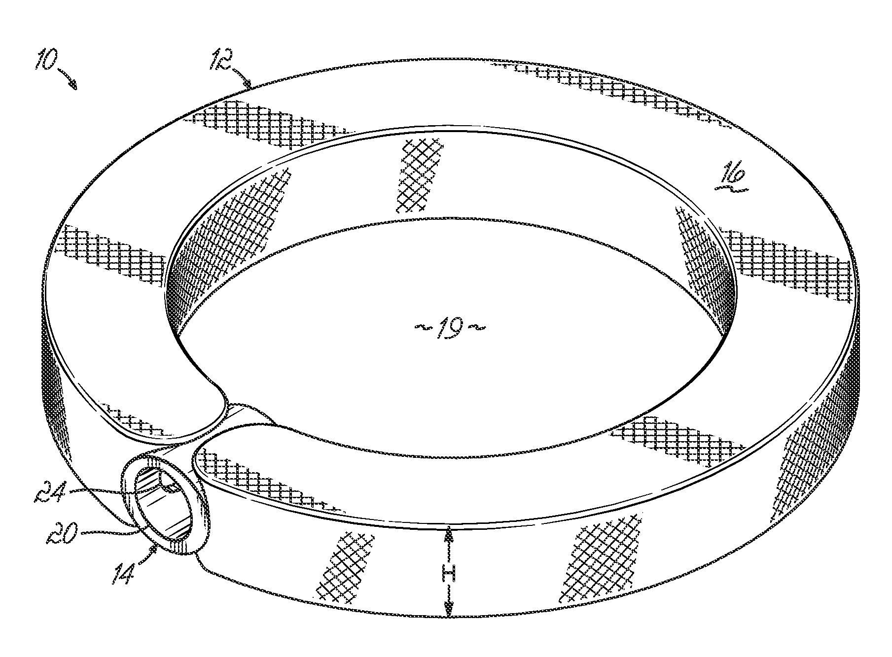
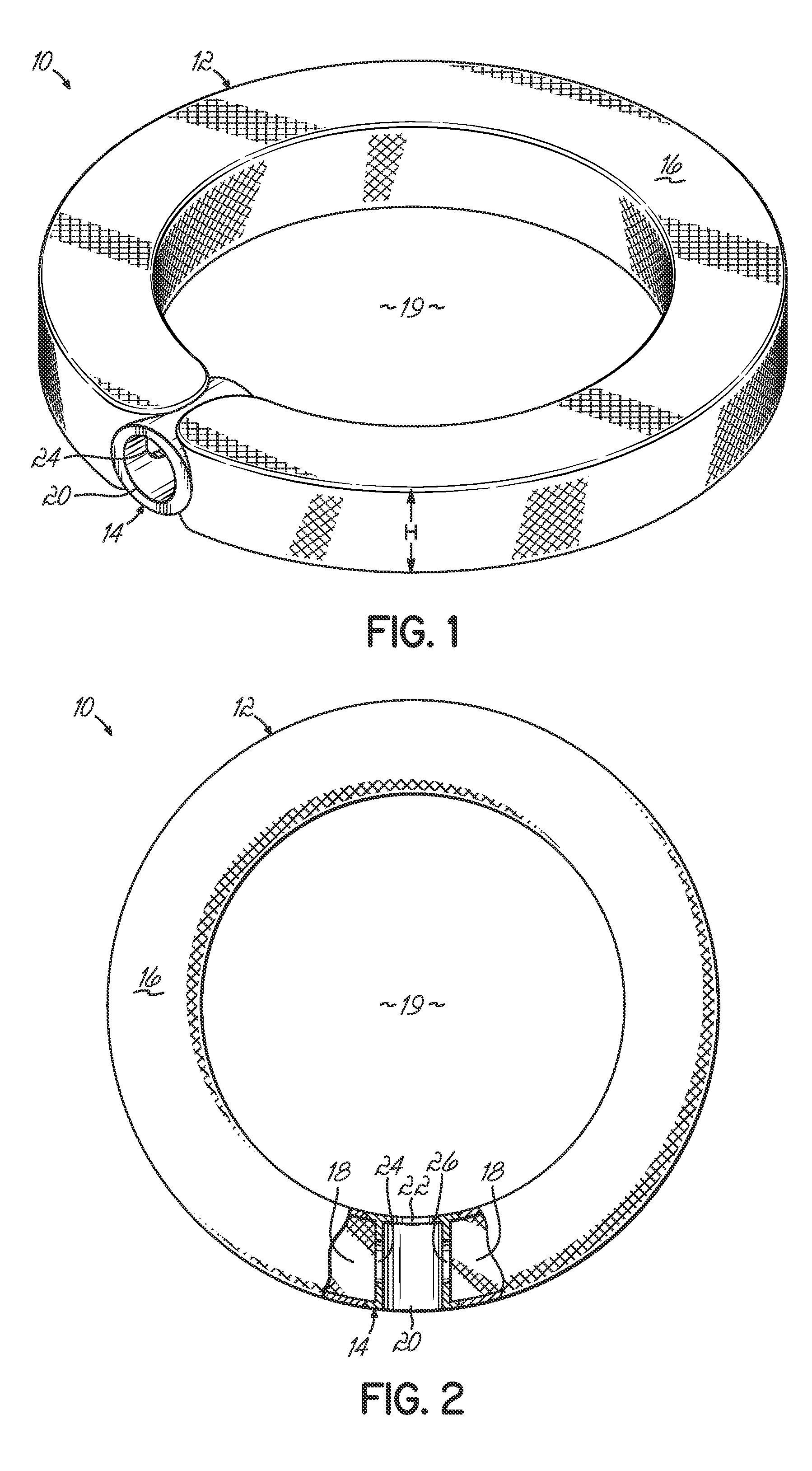
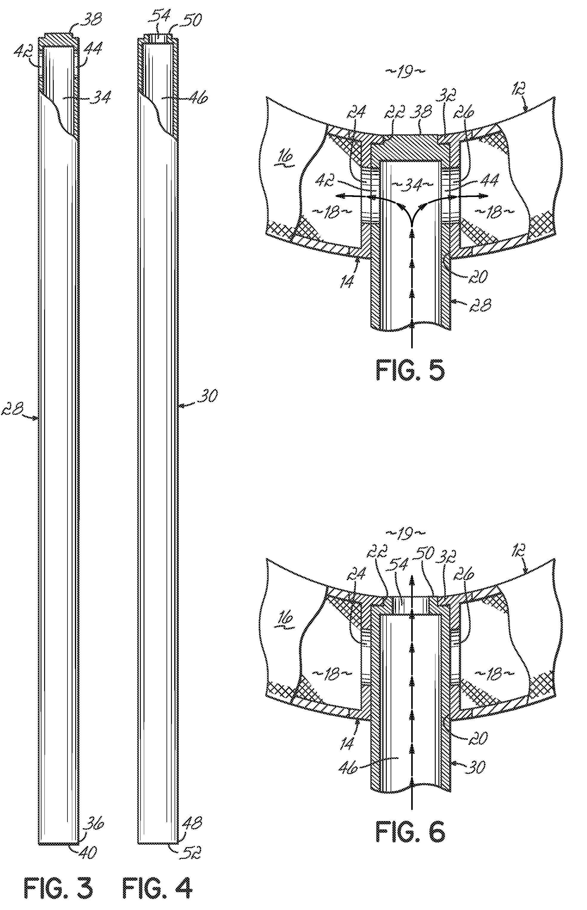
[0028]FIGS. 1 and 2 depict one embodiment of an interbody device 10 of the present invention. As shown, the interbody device 10 comprises a member 12 and a coupler 14. As will be discussed in detail later with reference to FIGS. 7-11, following a partial discectomy, the interbody device 10 is placed between adjacent vertebrae. Once placed, tubes (embodiments of which will be described herein) configured to removably cooperate with the coupler 14 may be used to fill the member 12 with material. In one embodiment, the interbody device 10 facilitates stabilization of a spine and also facilitates stabilization of adjacent vertebrae.

[0029]To that end, with reference once again to FIG. 1, the interbody device 10 with the member 12, shown in an expanded state, provides an anatomically contoured shape. While the interbody device 10 has a nearly ring-like perimeter, other shapes and configurations are possible. By way of example and not limitation, the interbody device 10 may be a customized...


PUM

PropertyMeasurementUnit
flexibleaaaaaaaaaa
volumeaaaaaaaaaa
internal volumeaaaaaaaaaa

Abstract

Methods and devices for insertion between adjacent vertebrae in a spine following removing at least a portion of a nucleus from within a disc. In one embodiment, the device includes a member having a flexible wall surrounding an internal volume and a coupler that is secured to the flexible wall. The member is adapted to expand when filled with a first filler material to form an interior cavity. The coupler has a first access point, a second access point, a first coupler side hole, and an optional second coupler side hole. The first and second access points are adapted to removably receive one or more fill tubes. The fill tubes cooperate with the first and optional second coupler side holes to direct the first filler material into the internal volume and a second filler material into the interior cavity.

Description

FIELD OF THE INVENTION[0001]This invention relates to orthopedic implants, and, more particularly, to interbody spinal devices.BACKGROUND OF THE INVENTION[0002]A spine includes a series of joints or motion segments. The components of each motion segment include two adjacent vertebrae, their apophyseal joints, an intervertebral disc, and connecting ligamentous tissue. Each motion segment is capable of flexion, extension, lateral bending, and translation. Each component of the motion segment contributes to these capabilities and to the mechanical stability of the spine.[0003]The intervertebral disc is one component that facilitates spine motion by allowing slight relative movement between adjacent intervertebral discs as well as holding the vertebrae together. The discs comprise an outer annulus fibrosus which surrounds and contains a nucleus pulposus. The nucleus acts as a shock absorber and a spacer to separate adjacent vertebra. In a healthy spine, the motion segments, including th...

Claims


Application Information

Patent Timeline
Patent Type & Authority Patents(United States)
IPC IPC(8): A61F2/44
CPCA61F2/441A61F2/4611A61F2002/302A61F2002/30586A61F2002/30884A61F2002/4475A61F2230/0065A61F2002/30593
Inventor HESTAD, HUGH D.HUDGINS, ROBERT GARRYLMAERTENS, JOHN
Owner ZIMMER SPINE INC
Why Eureka
Try Eureka