Method and system for optimal allocation of uplink transmission power in communication networks

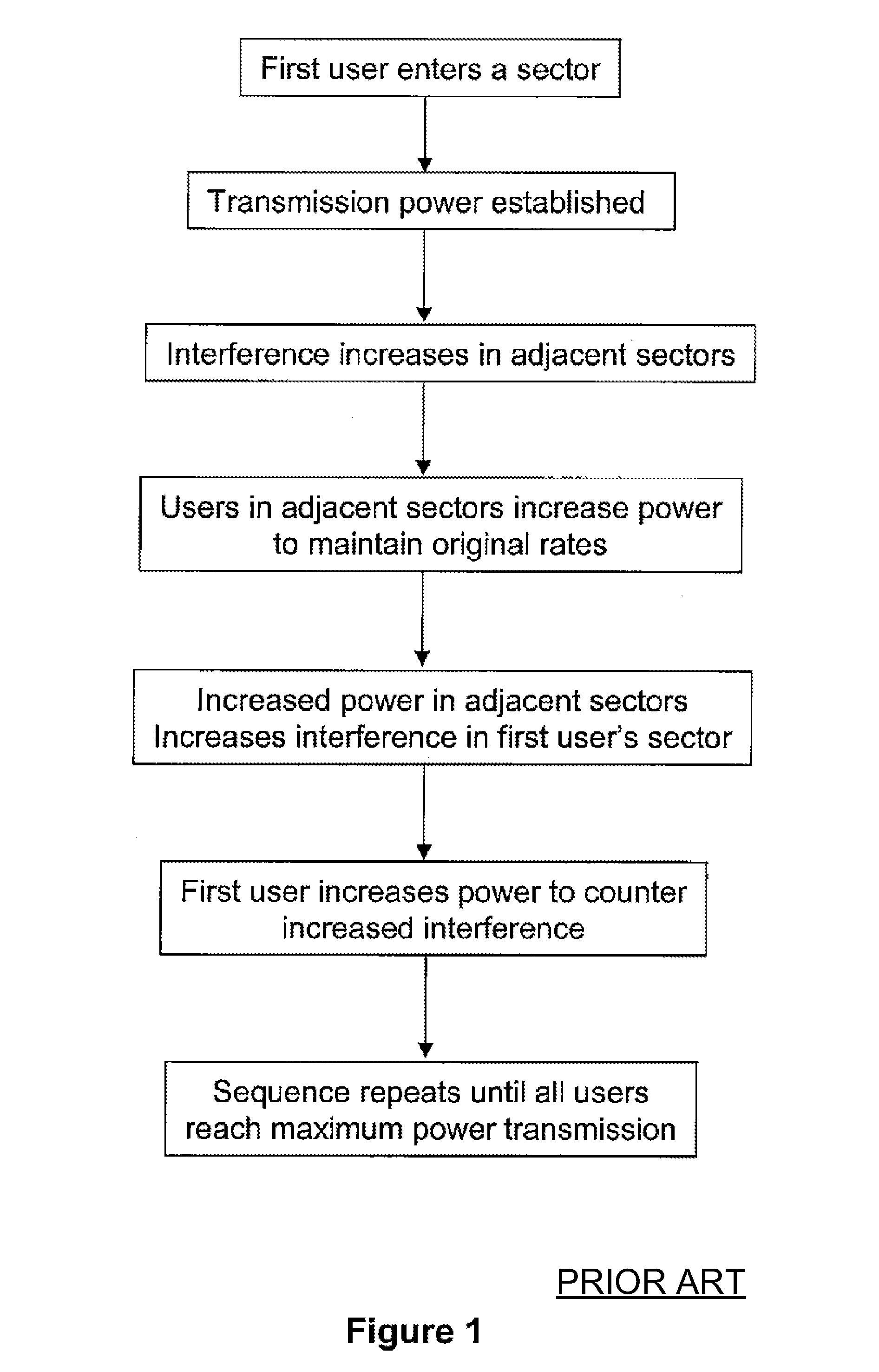
a communication network and transmission power technology, applied in the field of telecommunication techniques, can solve the problems of increasing the interference in the sector, severely restricting the signal to interference and noise ratio (sinr) achieved by the user, and still affecting the transmission user's inter-sector interference, so as to achieve a broader range of applicability

Inactive Publication Date: 2011-10-25
FUTUREWEI TECH INC
View PDF78 Cites 6 Cited by
  • Summary
  • Abstract
  • Description
  • Claims
  • Application Information

AI Technical Summary

Benefits of technology

[0017]The present invention generally relates to telecommunication techniques. More particularly, the present invention relates to a method for providing a scheme for network users to manage their transmission powers and inter-sector interferences in uplink wireless communications. More specifically, embodiments of the present invention allow optimal allocation of uplink transmission power for each user with fair management of inter-sector interference in an Orthogonal Frequency Division Multiple Access (OFDMA) network. But it would be recognized that the invention has a much broader range of applicability.
[0022]Numerous benefits may be achieved over pre-existing techniques using the present invention. In particular, embodiments in accordance with the present invention use a distributed algorithm in which each sector independently computes power allocation decision for the associated user based on local sector information. Certain embodiments of the present invention achieve high performance by operating the network system near the interference limit of an interference-limited sector. Other embodiments of the present invention also achieve fairness of the power allocation for each of the plurality of users within the system. Furthermore, some embodiments of the present invention provide an stable algorithm for managing the uplink transmission power allocation. For example, once a steady state is achieved, each AT continues to operate at the steady state power allocation until some change in the system occurs. Changes will of course occur because of variations in the radio conditions of each AT. Depending upon the embodiment, one or more of these benefits may be achieved. These and other benefits may be described throughout the present specification and more particularly below.

Problems solved by technology

However, the user AT transmission is still affected by inter-sector interference since other users in adjacent sectors may also have been assigned to the same tile.
If those users in the adjacent sectors transmitted with high power then the inter-sector interference may severely limit the signal to interference and noise ratio (SINR) achieved by the user.
The increased power of users in the adjacent sectors results in an increase in the interference in the sector;
Such an approach leads to a result that all users transmit with maximum power which is not an optimal use of uplink resources.
In general, simply maintaining interference level within a set limit will not result in an optimal or fair solution.
Even if only one user is transmitting, its rate is limited because of the limit placed on the interference it causes on the second sector.
Clearly this is not optimal.
The third user then cannot transmit because doing so will cause the interference constraint for the second sector to be violated.
This demonstrates that the system may not be fair.
Hence the solution is non-unique and this may potentially result in instability.
Certain conventional techniques based on the framework for dealing the above problem are often not adequate for various reasons.
These conventional solutions require the exchange of a large amount of information and the delay in collecting this information may mean that the computed solution is no longer optimal when applied.

Method used


Image

  • Method and system for optimal allocation of uplink transmission power in communication networks
  • Method and system for optimal allocation of uplink transmission power in communication networks
  • Method and system for optimal allocation of uplink transmission power in communication networks

Examples


Embodiment Construction

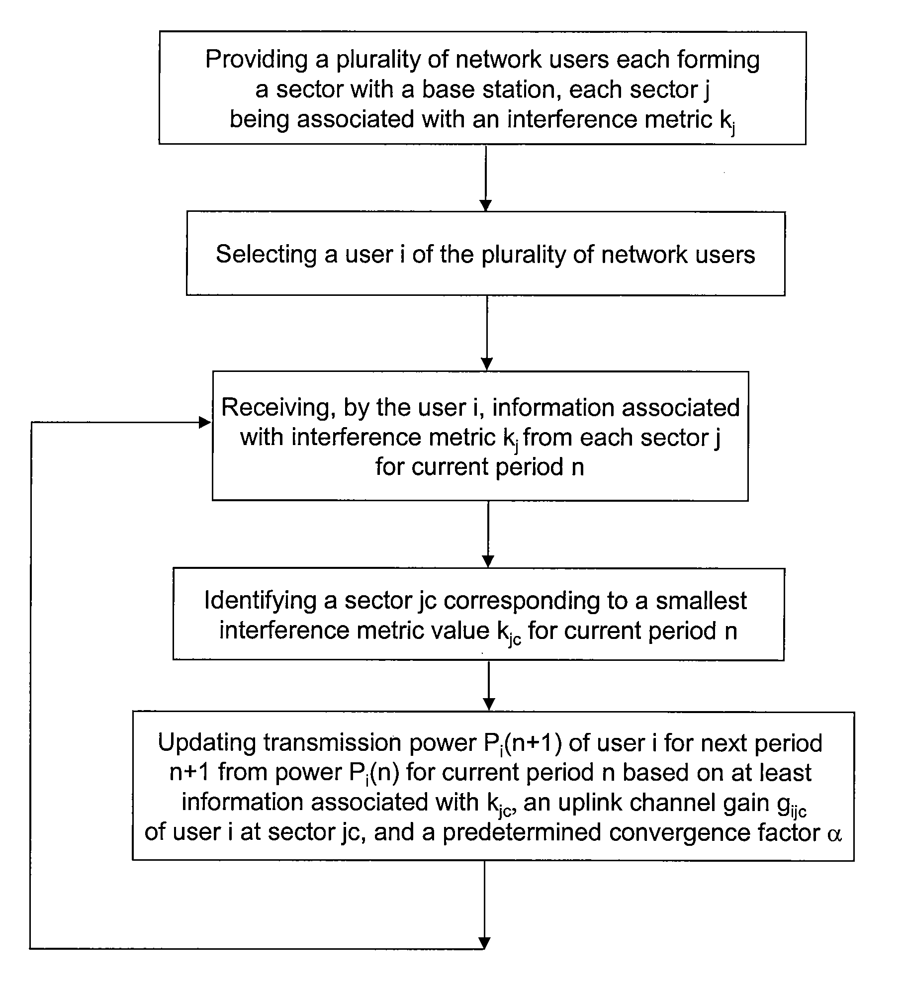
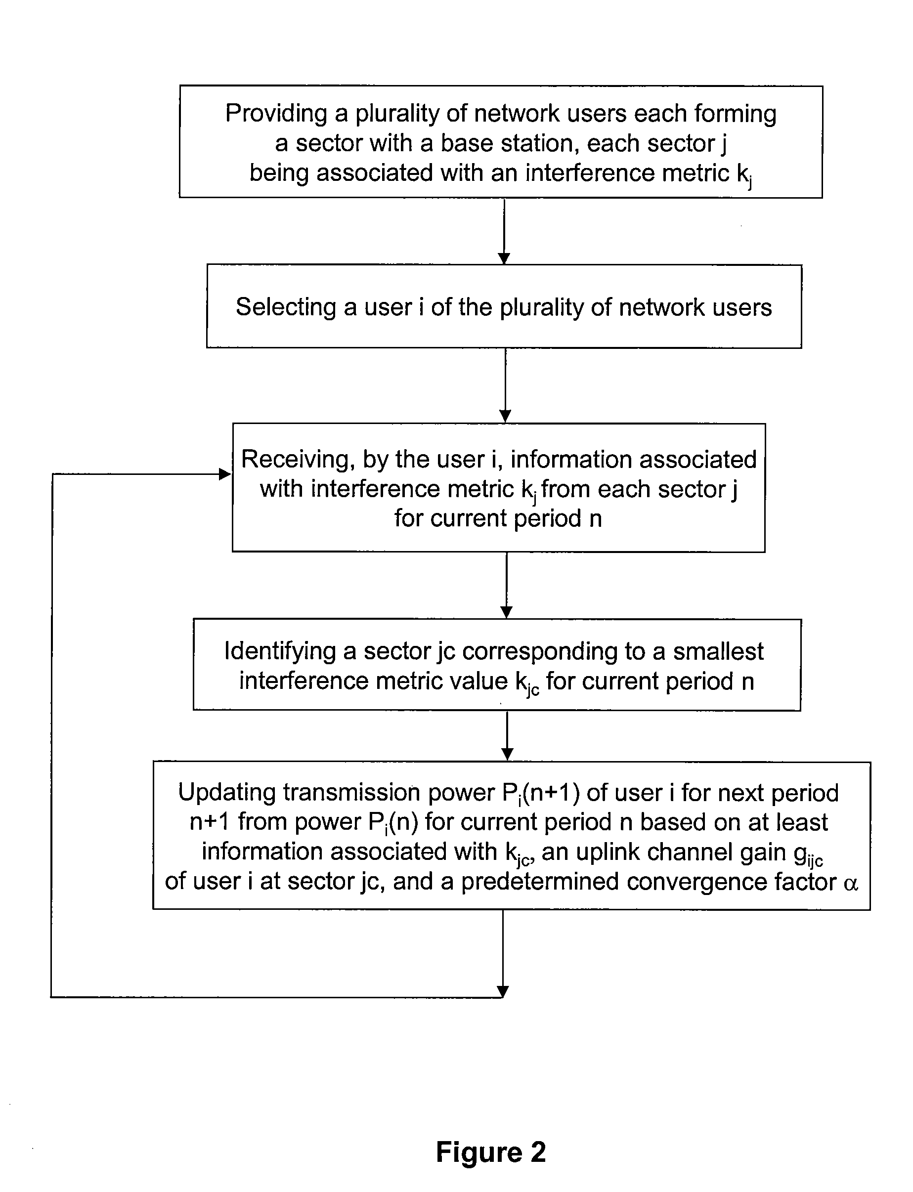
[0029]The present invention generally relates to telecommunication techniques. More particularly, the present invention relates to a method for providing a scheme for network users to manage their transmission powers and inter-sector interferences in uplink wireless communications. More specifically, embodiments of the present invention allows optimal allocation of uplink transmission power for each user with fair management of inter-sector interference in an Orthogonal Frequency Division Multiple Access (OFDMA) network. But it would be recognized that the invention has a much broader range of applicability.

[0030]The uplink frame of an OFDMA network consists of a set of tiles. Each tile consists of a set of subcarriers. In some cases these subcarriers may be spread over the entire bandwidth to provide frequency diversity for the corresponding transmissions. In other cases the tile consists of a subset of consecutive subcarriers and the channel conditions as well as the interference ...


PUM


Abstract

A method for determining transmission power for a user in a network. The method includes receiving a plurality of interference indicators by a user which is associated with a sector. The plurality of interference indicators corresponds to a plurality of sectors respectively each associated with one of a plurality of users and a base station. The method further includes processing at least information associated with the plurality of interference indicators and selecting an interference indicator based on at least information associated with the plurality of interference indicators. The selected interference indictor corresponds to one of the plurality of sectors. Additionally, the method includes determining a gain indicator corresponding to both the user and the one of the plurality of sectors, and processing information associated with the gain indicator. Moreover, the method includes determining a transmission power of the user based on at least information associated with the gain indicator and the selected interference indictor.

Description

CROSS-REFERENCES TO RELATED APPLICATIONS[0001]This application claims priority to U.S. Provisional Patent Application No. 60 / 835,573, filed on Aug. 4, 2006, commonly assigned, incorporated by reference herein for all purposes.STATEMENT AS TO RIGHTS TO INVENTIONS MADE UNDER FEDERALLY SPONSORED RESEARCH OR DEVELOPMENT[0002]NOT APPLICABLEREFERENCE TO A “SEQUENCE LISTING,” A TABLE, OR A COMPUTER PROGRAM LISTING APPENDIX SUBMITTED ON A COMPACT DISK[0003]NOT APPLICABLEBACKGROUND OF THE INVENTION[0004]The present invention generally relates to telecommunication techniques. More particularly, the present invention relates to a method for providing a scheme for network users to manage their transmission powers and inter-sector interferences in uplink wireless communications. More specifically, embodiments of the present invention allows optimal allocation of uplink transmission power for each user with fair management of inter-sector interference in an Orthogonal Frequency Division Multiple ...

Claims


Application Information

Patent Timeline
Patent Type & Authority Patents(United States)
IPC IPC(8): H04B7/00
CPCH04W52/146H04B17/382H04B17/345H04W52/34
Inventor HOSEIN, PATRICK
Owner FUTUREWEI TECH INC
Why Eureka
Try Eureka