Cutting device

a cutting device and cutting head technology, applied in the field of cutting devices, can solve the problems of rotary cutter operating at a less than desirable level and the blade moving to a small extent, and achieve the effect of preventing users from being accidentally cu

Active Publication Date: 2011-11-01
OY FISKARS AB
View PDF73 Cites 41 Cited by
  • Summary
  • Abstract
  • Description
  • Claims
  • Application Information

AI Technical Summary

Benefits of technology

[0005]Various embodiments provide an improved cutting device including a mechanism for selectively guarding the edge of a cutting blade. According to various embodiments, a sliding mechanism is operatively connected to a blade guard, wherein the translational movement of the sliding mechanism causes a corresponding rotational movement of the blade guard. When the blade guard is in an extended position, the edge of the cutting blade is not exposed, thereby preventing a user from being accidentally cut by the blade.
[0006]Various embodiments also provide for an improved blade replacement system. According to various embodiments, a locking member is capable of lifting the cutting blade without the user having to touch the blade itself. When the user wishes to replace the blade, the locking member is used to remove the old blade from the rotary cutter and place the old blade in a used blade storage region. The locking member may then be used to lift a new blade from a new blade storage region and correctly position the new blade on the rotary cutter.

Problems solved by technology

Although a variety of conventional handheld rotary cutters are available, many such cutters possess a number of drawbacks.
This is undesirable since it poses a safety hazard.
However, such mechanisms can also result in the blade moving to a small extent during use, since the mechanism to which the blade is operatively connected inherently may have a certain amount of “give” or looseness.
This can result in the rotary cutter operating at a less than desirable level.

Method used


Image

  • Cutting device
  • Cutting device
  • Cutting device

Examples


Embodiment Construction

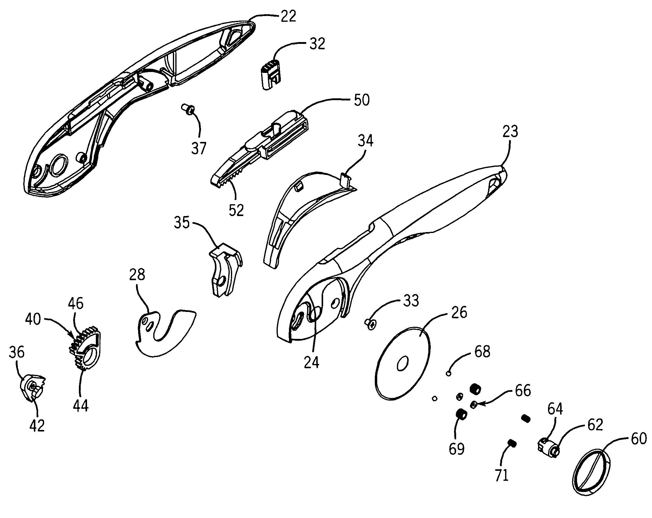
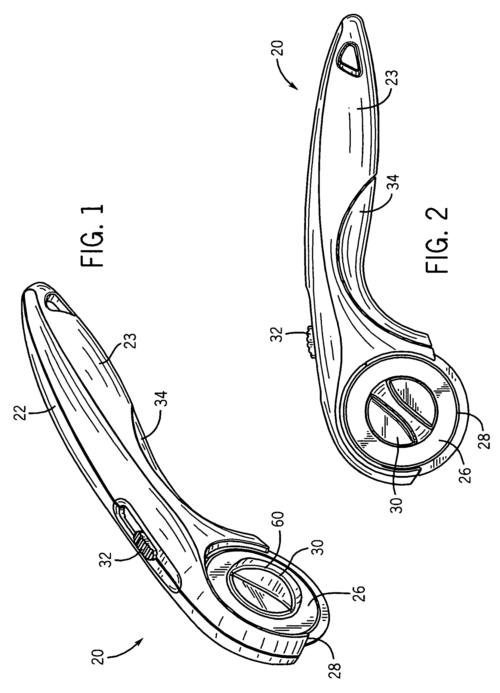
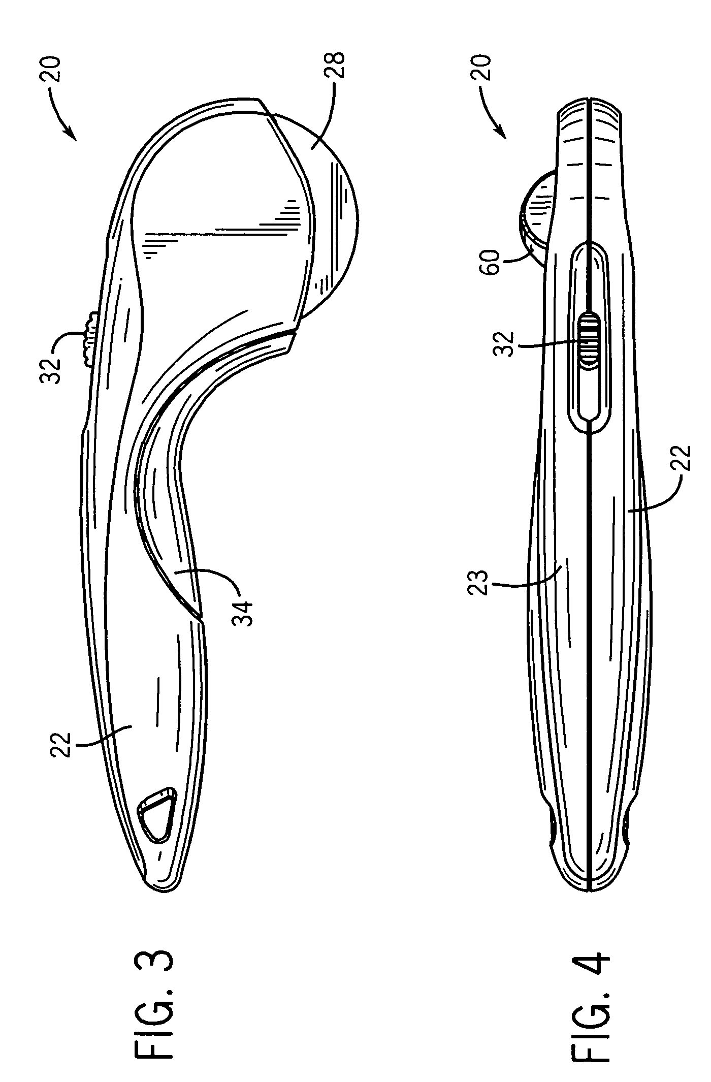
[0022]FIGS. 1-7 show a hand-held rotary cutter 20 according to one particular embodiment of the present invention. As shown in FIGS. 1-7, the rotary cutter 20 includes a first housing portion 22 operatively connected to a second housing portion 23. As shown in FIG. 8, for example, the first and second housing portions 22 and 23 may be operatively connected to each other by a housing securement member 33 that passes through a baffle 35. An additional fastener 37 may also be used to secure the first and second housing portions 22 and 23 to each other.

[0023]The second housing portion 23 includes a blade acceptance region 24 for accepting a cutting blade 26 and a blade guard 28. As discussed below, the blade guard 28 is selectively positionable so as to prevent the user from being accidentally being cut by the cutting blade 26 when the rotary cutter is not in use. The selective positioning of the blade guard 28 is accomplished using a trigger mechanism, in the form of a slide member 32 ...


PUM

PropertyMeasurementUnit
magneticaaaaaaaaaa
rotational movementaaaaaaaaaa
movementaaaaaaaaaa

Abstract

An improved cutting device including a mechanism for selectively guarding the edge of a cutting blade. According to various embodiments, a sliding mechanism is operatively connected to a blade guard, wherein the translational movement of the sliding mechanism causes a corresponding rotational movement of the blade guard. When the blade guard is in an extended position, the edge of the cutting blade is not exposed, thereby preventing a user from accidentally cut by the blade. Various embodiments also provide for an improved blade replacement system. According to various embodiments, a locking member is capable of lifting the cutting blade without the user having to touch the blade itself.

Description

FIELD OF THE INVENTION[0001]The present invention relates generally to cutting devices. More particularly, the present invention relates to rotary cutting devices used to cut various types of materials.BACKGROUND OF THE INVENTION[0002]This section is intended to provide a background or context to the invention that is recited in the claims. The description herein may include concepts that could be pursued, but are not necessarily ones that have been previously conceived or pursued. Therefore, unless otherwise indicated herein, what is described in this section is not prior art to the description and claims in this application and is not admitted to be prior art by inclusion in this section.[0003]Handheld rotary cutters are commonly used to cut layers of fabric, cardboard, paper, vellum or other materials. Rotary cutters typically include a body with a handle attached thereto for gripping by a user. A generally circular head includes a surface to which a substantially circular cuttin...

Claims


Application Information

Patent Timeline
Patent Type & Authority Patents(United States)
IPC IPC(8): B26B3/06B26B29/02
CPCB26B29/02B26B25/005B26D7/22
Inventor EBY, DAVID C.DUSK, CHRISTINELAM, LUCALLING, JON
Owner OY FISKARS AB
Why Eureka
Try Eureka