
Plastic working method and plastic working system

a working method and working system technology, applied in the field of plastic working method and plastic working system, can solve the problems of loop controller installation position, material being fed erroneously, coil material vibrating and flapping in some cases, etc., and achieve the effect of reducing the influence of flapping

Active Publication Date: 2011-11-01
DENSO CORP +1
View PDF10 Cites 1 Cited by
  • Summary
  • Abstract
  • Description
  • Claims
  • Application Information

AI Technical Summary

Benefits of technology

[0013]The present invention has been accomplished to solve the above problems. An object of the present invention is to provide a plastic working method and plastic working system in which a plurality of plastic working devices are arranged, characterized in that: a loop of a workpiece intermittently outputted from a preceding plastic working device is watched and the workpiece is continuously sent out to the succeeding plastic working device so as to reduce an influence of the flapping of the workpiece located between the press devices and the workpiece can be stably fed to the succeeding plastic working device.
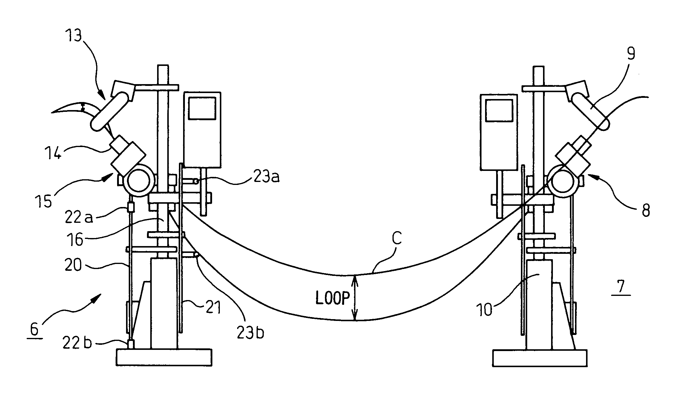
[0015]Due to the foregoing, for the coil material (C) intermittently sent out from the plastic working device (2), the operation of the plastic working device (2) is controlled and the feeding speed of the feed adjusting device (6) is controlled when a slack of the coil material (C) caused by intermittent feeding is watched and also when a slack of the coil material (C) sent out from the feed adjusting device (6) is watched. Due to the foregoing, a problem of the phenomenon of flapping of the coil material (C) caused by intermittent feeding of the coil material (C) can be solved and the coil material (C) can be stably fed to the succeeding plastic working device (2).
[0024]Due to the foregoing, it is possible to realize a press working system, the productivity of which is enhanced.
[0026]Due to the foregoing, a workpiece can be stably fed to the next plastic working device (2b) and it is possible to build a system which is not influenced by an intermittent feeding operation of the preceding plastic working device (2a).
[0028]When intermittent feeding of the coil material (C) is converted to continuous feeding, it is possible to prevent flapping. Therefore, the slack of the coil material (C) can be easily watched.

Problems solved by technology

Which results in the coil material vibrating and flapping in some cases.
When the coil material flap as described above, not only the intermittently feeding mechanism receives an excessively heavy load, but also the coil material is bent and damaged which results in the material being erroneously fed.
Therefore, to form an appropriate loop, loop controller's installation position becomes a problem.
Accordingly, improvement in production capacity is limited.
However, this coil material supply device is disadvantageous in that even when the plurality of press devices are arranged in series to each other, a feed mechanism incorporated into each press device is intermittently operated.
Therefore, due to the flapping generated in a workpiece located between the press devices, erroneous feeding is induced in the press device arranged before and after the coil material supply device.
Accordingly, it is only possible to execute a low speed synchronous operation.
Therefore, it is difficult to enhance productivity.
However, the repetitive accuracy of the continuous feed type device is lower than that of the intermittent type device.
Further, when the operation speed is increased, there is a fault that the decrease in accuracy repeatedly becomes remarkable.

Method used


Image

  • Plastic working method and plastic working system
  • Plastic working method and plastic working system
  • Plastic working method and plastic working system

Examples


Embodiment Construction

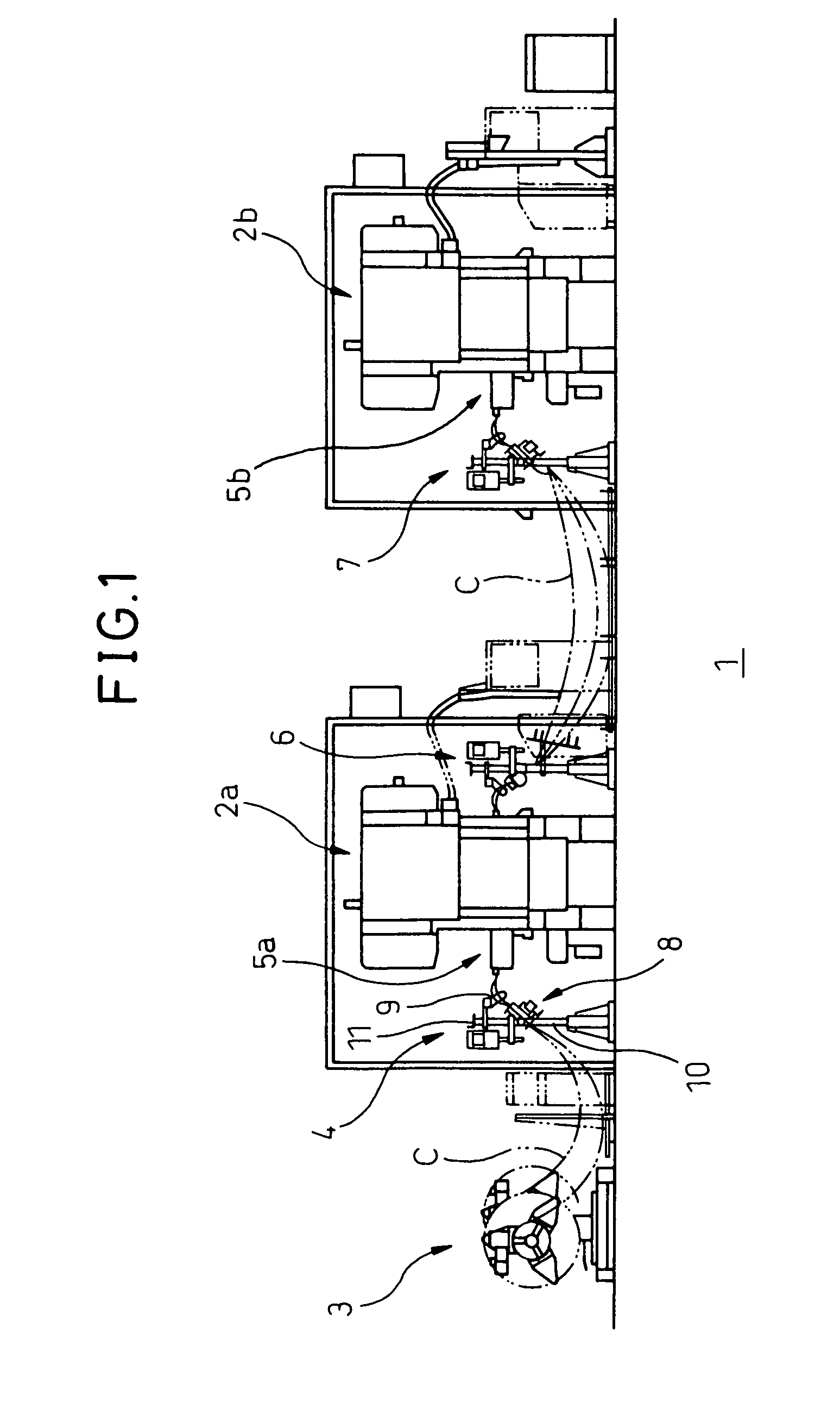
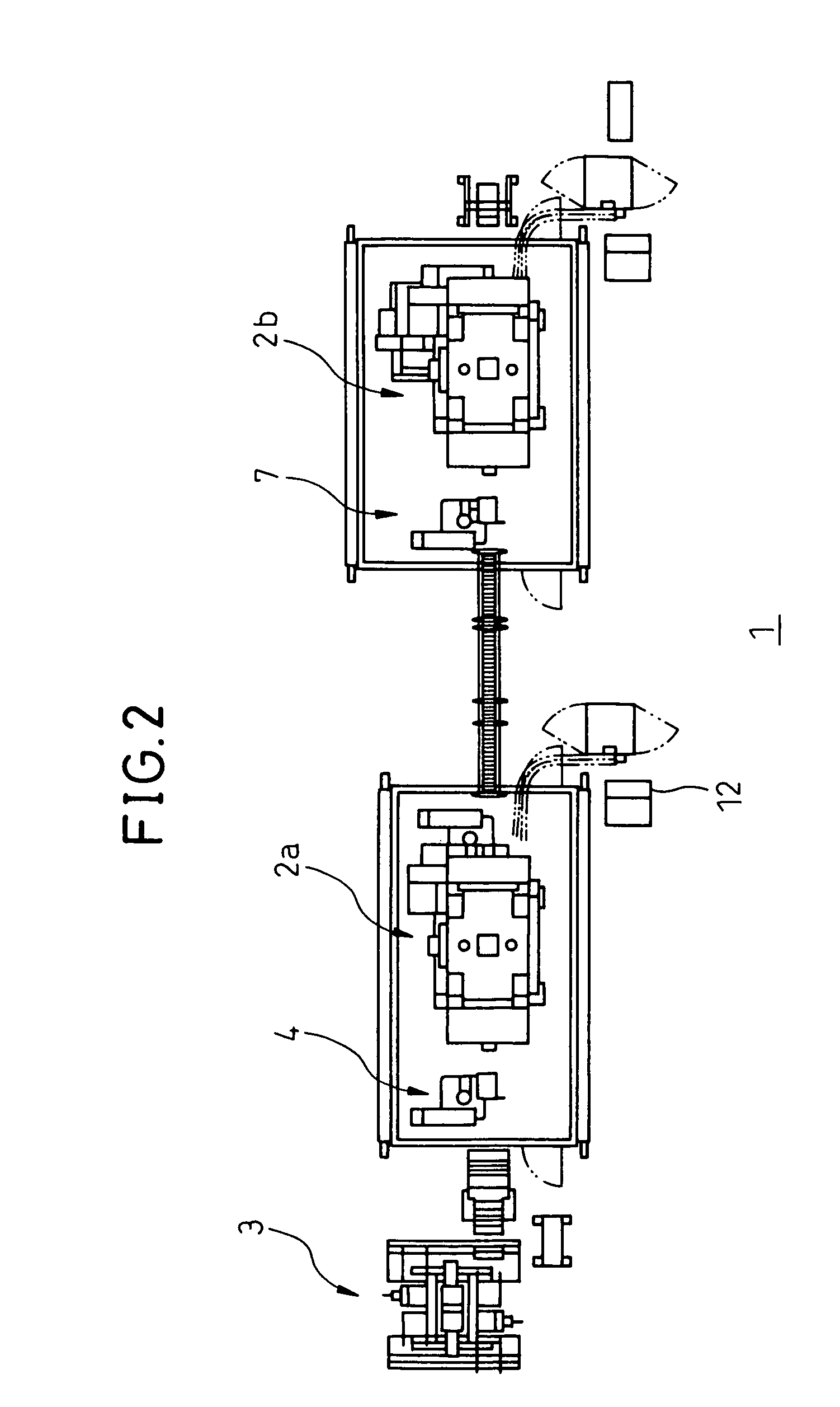
[0036]FIG. 1 is a view showing a press working line 1 which is an example of the plastic working system of the present invention.

[0037]This press working line 1 includes two press devices 2 for conducting a predetermined press working on a coil material C which is a workpiece. These two press devices 2 will be referred to as a first press device 2a and a second press device 2b, hereinafter.

[0038]In other words, the press working line 1 includes: an uncoiler 3 which is a delivering means for delivering the coil material C; a first feeding device 4; an intermittently feeding mechanism 5a; a first press device 2a which is a preceding press device; a feed adjusting means 6; a second feeding device 7; an intermittently feeding mechanism 5b; and a second press device 2b which is a succeeding press device.

[0039]The first and the second press device 2a, 2b respectively have a metallic mold for executing a predetermined press working. In this connection, the fundamental constitution of the f...


PUM

PropertyMeasurementUnit
speedaaaaaaaaaa
feeding speedaaaaaaaaaa
timeaaaaaaaaaa

Abstract

A plurality of press devices 2 are arranged in a plastic working system. The plastic working system includes: a loop correction sensor 13 for watching a slack of a coil material C intermittently delivered from a preceding first press device 2a; and a second slack watching means 19 for watching a slack of the coil material C generated at the time of sending the coil material C to a succeeding second press device 2b. According to the slack generated by intermittent feeding of the coil material C sent from the first press device 2a, intermittent feeding is converted to continuous feeding by the feeding means 15. At the same time, the continuous feeding speed is subjected to speed increasing / decreasing control. On the other hand, by the second slack watching means 19, a slack of the coil material C is watched at the time of feeding the coil material C to the second press device 2b and the preceding first press device 2a is subjected to speed increasing / decreasing control.

Description

BACKGROUND OF THE INVENTION[0001]1. Technical Field of the Invention[0002]The present invention relates to a plastic working method and plastic working system, in the working line of which a plurality of plastic working devices are arranged and a workpiece can be smoothly supplied to the working devices and a high speed operation can be executed.[0003]2. Description of the Related Art[0004]In a conventional plastic working device, for example, a conventional press device is incorporated into a press working line to which a coil material, which is a workpiece, is supplied so that it can be worked by press working, the coil material is delivered from an uncoiler which holds and uncoils the coil material and the coil material is made to pass through a leveler which straightens the coil material and also made to pass through a section, in which a loop (slack or loosening) is generated, and the coil material is sent to a press device through an intermittently feeding mechanism so that th...

Claims


Application Information

Patent Timeline
Patent Type & Authority Patents(United States)
IPC IPC(8): B21B37/48
CPCB21C49/00B21D43/04
Inventor KONDO, FUMIOTAKENOUCHI, SHOICHINAKANISHI, TAKAYUKIMATSUI, OSAMU
Owner DENSO CORP
Learn More