Mount structure

a technology for mounting structures and displays, applied in the direction of furniture parts, electrical apparatus casings/cabinets/drawers, instruments, etc., can solve the problems of increasing packing costs, affecting assembly and use, and low package utility, so as to enhance the structural strength of the structure, reduce the cost of packing, and reduce the space utility of the package

Active Publication Date: 2011-11-01
AMTRAN TECH CO LTD
View PDF5 Cites 6 Cited by
  • Summary
  • Abstract
  • Description
  • Claims
  • Application Information

AI Technical Summary

Benefits of technology

[0008]The bottom base and the support column of the conventional mount structure are integrally formed. Therefore, during the packing process for delivery, it is impossible to separate the bottom base from the support column, so that the space utility of package is relatively low, and meanwhile the packing cost is increased. Further, as the integrally formed mount is mainly adapted to assemble a thin display with a small size, if the mount is applied to a thin display with a large size, problems on assembly and usage may occur due to overweight.
[0009]A mount structure provided by the present invention includes a base and a bearer, for holding a display. The base has a slot on a surface. At least a combining block is disposed protruding from the slot, and the combining block has at least a suspending hook. The bearer has a bearing portion and a combining portion. The bearing portion is used for being combined to the display, and the combining portion has at least a corresponding buckle hole with the same number as the hook on the combining block and a plurality of reinforcing ribs. The combining portion is installed in the slot of the base, and fixed therein by various means in addition to being engaged in the buckle hole through the hook, such as by correspondingly inserting a latch of the combining portion in a hole on the combining block, or using a screw passing through a tap hole of the combining portion and a perforation of the combining block. Further, the mount of the present invention further enhances the structural strength thereof for holding the display through the reinforcing ribs.
[0010]The efficacies of the present invention are as follows. A slot, for installing the bearer, is disposed on the base, so as to save the height space of the mount of the present invention. Meanwhile, as the center of gravity of the mount after the display is mounted thereon is relatively low, a higher stability is achieved. Further, through combing means such as the hooks, latches, bumps, and screws disposed on the bearer, the bearer is stably installed in the base. Moreover, a reinforcing rib structure is disposed on a lateral edge of the bearer, such that the overall strength and rigidity of the mount are greatly improved, and the mount is enabled to hold a thin display of a large size without being damaged. In addition, the base and the bearer of the mount of the present invention are separately formed, thus the packing cost is lowered while increasing the load capability of the container during transportation.

Problems solved by technology

Therefore, during the packing process for delivery, it is impossible to separate the bottom base from the support column, so that the space utility of package is relatively low, and meanwhile the packing cost is increased.
Further, as the integrally formed mount is mainly adapted to assemble a thin display with a small size, if the mount is applied to a thin display with a large size, problems on assembly and usage may occur due to overweight.

Method used


Image

  • Mount structure
  • Mount structure
  • Mount structure

Examples


first embodiment

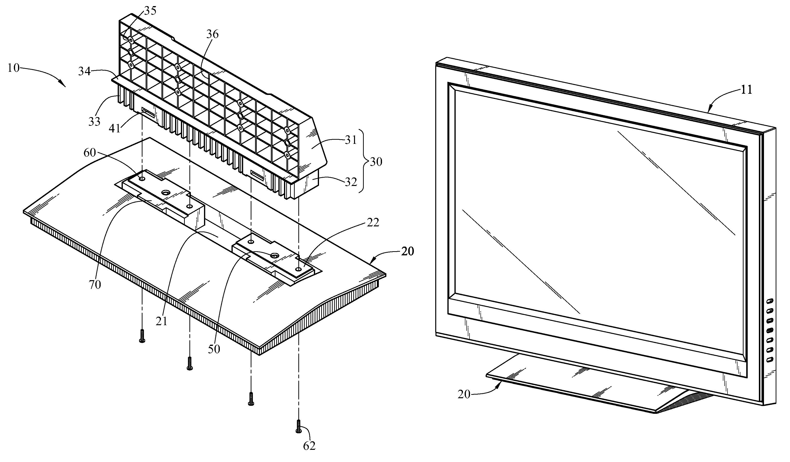
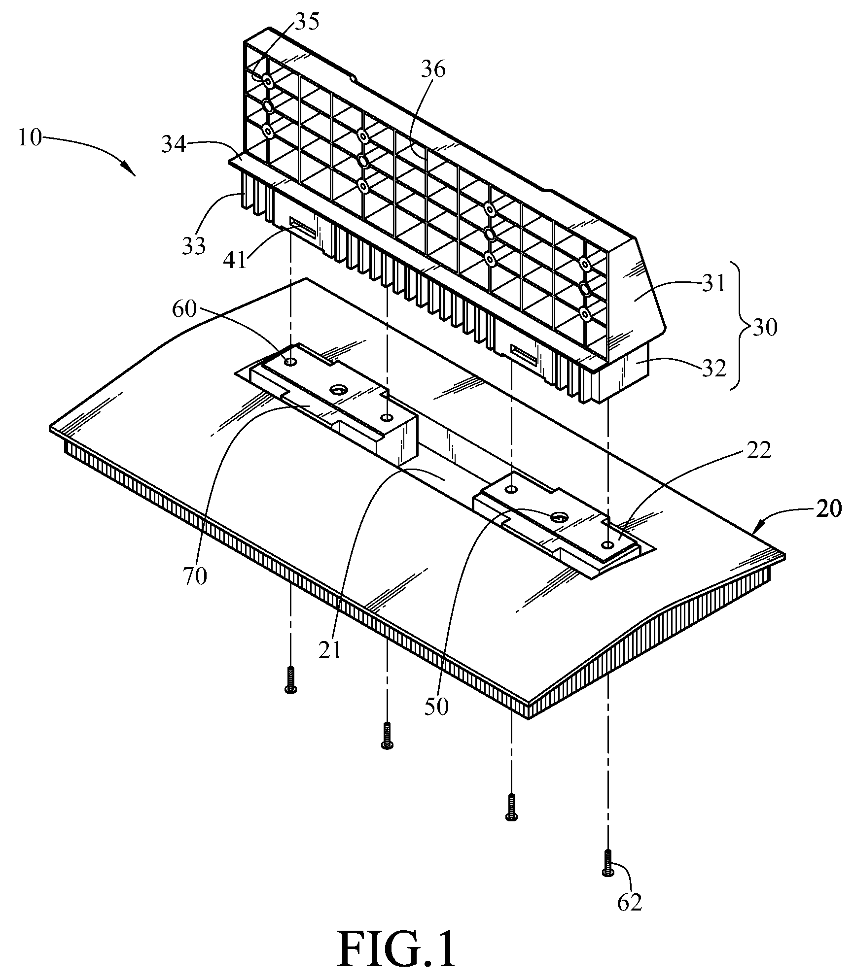
[0024]Referring to FIGS. 1 to 5, schematic views of the present invention are shown. A mount structure of the present invention includes a base 20 and a bearer 30.

[0025]The base 20 has a surface of a quasi-trapezoidal structure with a relatively higher central part and two lower sides. A slot 21 is opened on an upper surface of the base 20, and two combining blocks 22 are disposed on and protrudent from the slot 21. The bearer 30 has a bearing portion 31 and a combining portion 32, the bearing portion 31 is used for being combined to the display 11, and the combining portion 32 is used for being installed in the slot 21, such that the bearer 30 is stably installed on the base 20.

[0026]Suspending hooks 40 are respectively disposed on two sides of each combining block 22 corresponding to the combining portion 32. Buckle holes 41 with the same number as the hooks 40 are disposed on one side of the combining portion 32 opposite to the base 20 and corresponding to the hooks 40. When the ...

second embodiment

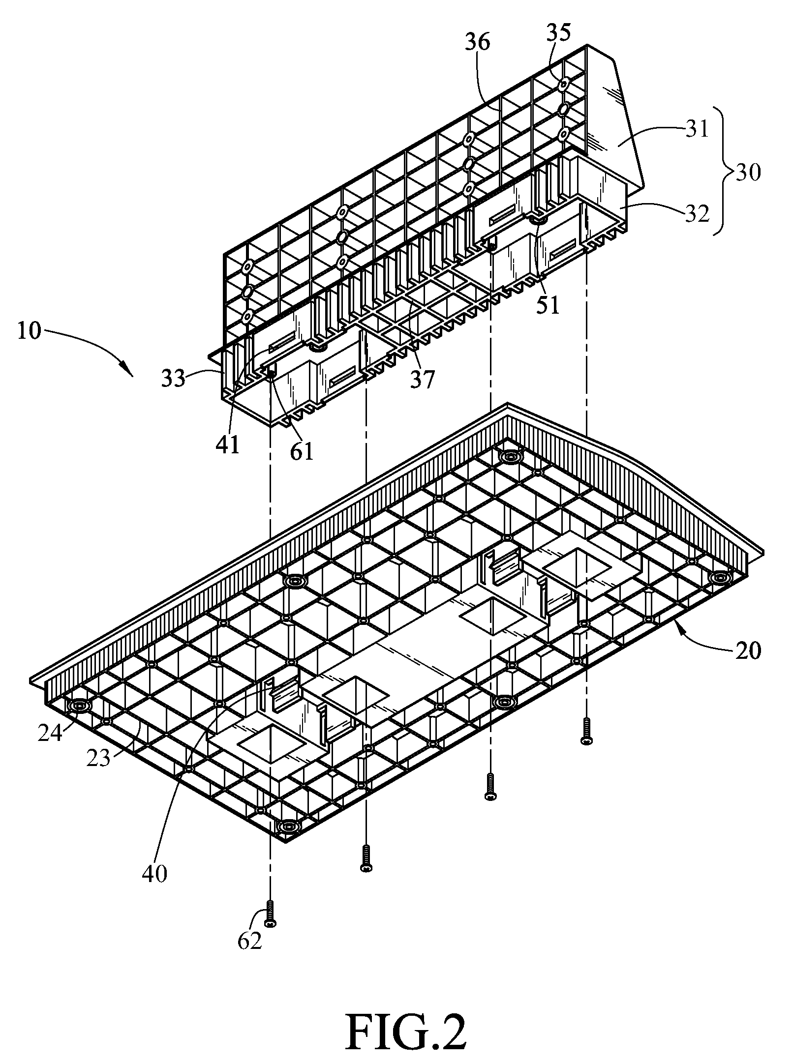
[0034]Referring to FIGS. 7 and 8, schematic views of the present invention are shown, in which symbols of FIGS. 1 to 4 are employed. A mount structure of the present invention includes a base 20 and a bearer 30. The base 20 has a surface of a quasi-trapezoidal structure with a relatively higher central part and two lower sides. A slot 21 is opened on an upper surface of the base 20, and two combining blocks 22 are disposed protruding from the slot 21. The bearer 30 has a bearing portion 31 and a combining portion 32, the bearing portion 31 is used for being combined to the display 11 (referring to FIG. 5), and the combining portion 32 is used for being installed in the slot 21, such that the bearer 30 is stably installed on the base 20. Suspending hooks 40 are respectively disposed on two sides of the combining block 22 corresponding to the combining portion 32, and buckle holes 41 with the same number as the hooks 40 are disposed on one side of the combining portion 32 opposite to ...

third embodiment

[0037]Referring to FIG. 9, a schematic view of the present invention is shown, in which numerals of FIGS. 1 to 4 are employed. A mount structure of the present invention includes a base 20 and a bearer 30. A slot 21 (referring to FIG. 1) is opened on an upper surface of the base 20, and two combining blocks 22 (referring to FIG. 1) are disposed protruding from the slot 21. The bearer 30 has a bearing portion 31 and a combining portion 32, the bearing portion 31 is used for being combined to the display 11 (referring to FIG. 5), and the combining portion 32 is used for being installed in the slot 21, such that the bearer 30 is stably installed on the base 20. Buckle holes 41 are respectively disposed on two sides of each combining block 22 corresponding to the combining portion 32, and hooks 40 with the same number as the buckle holes 41 are disposed on one side of the combining portion 32 opposite to the base 20 and corresponding to the buckle holes 41. When the combining portion 32...


PUM


Abstract

A mount structure includes a base and a bearer. The base has a slot, and at least one combining block is disposed protruding from the slot. The bearer has a bearing portion and a combining portion. The bearing portion is connected to a display, and the combining portion is installed in the slot through hooks, buckles, latches, screws, or other combining methods, such that the bearer is fixed on the base. Moreover, the combining portion is provided with reinforcing ribs for enhancing the structural strength of the bearer.

Description

CROSS-REFERENCE TO RELATED APPLICATIONS[0001]This non-provisional application claims priority under 35 U.S.C. §119(a) on Patent Application No(s). 097212689 filed in Taiwan, R.O.C. on Jul. 16, 2008 the entire contents of which are hereby incorporated by reference.BACKGROUND OF THE INVENTION[0002]1. Field of Invention[0003]The present invention relates to a mount structure, and more particularly to a mount structure for holding a display.[0004]2. Related Art[0005]Since TV sets are invented, consumers may enjoy the fanciest events worldwide at home, so as to be entertained while gaining knowledge. The TV set develops from the earliest cathode ray tube (CRT) to the recently most popular liquid crystal display (LCD), plasma display panel (PDP), and the like. Meanwhile, the TV set also changes from the early thick and heavy type of CRT to the current lighter and thinner type of LCD and PDP, such that it is possible for the user to install a thin display of a large size in a small indoor ...

Claims


Application Information

Patent Timeline
Patent Type & Authority Patents(United States)
IPC IPC(8): A47B91/00
CPCF16M11/00F16M11/22F16M2200/08Y10S248/917
Inventor TAI, CHUN-PING
Owner AMTRAN TECH CO LTD
Why Eureka
Try Eureka