Foldable propeller, power assembly and unmanned aerial vehicle
a technology of power assembly and propeller, which is applied in the field can solve the problems of increasing the wear of the propeller mounted on the rear-end power assembly, affecting the reliability of unmanned aerial vehicles, and large size so as to improve the spatial utilization, facilitate the carrying of unmanned aerial vehicles, and improve the reliability
- Summary
- Abstract
- Description
- Claims
- Application Information
AI Technical Summary
Benefits of technology
Problems solved by technology
Method used
Image
Examples
embodiment 1
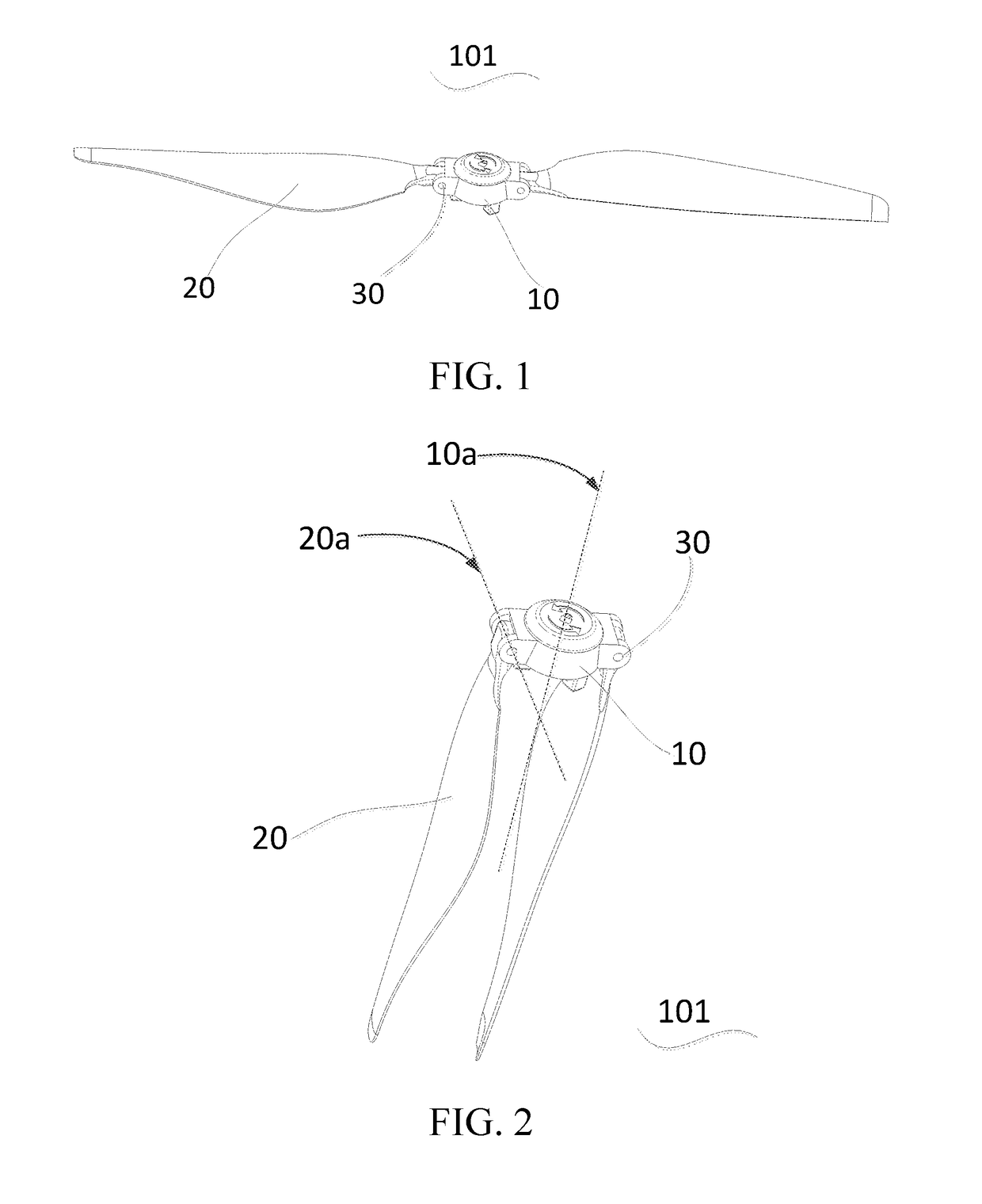
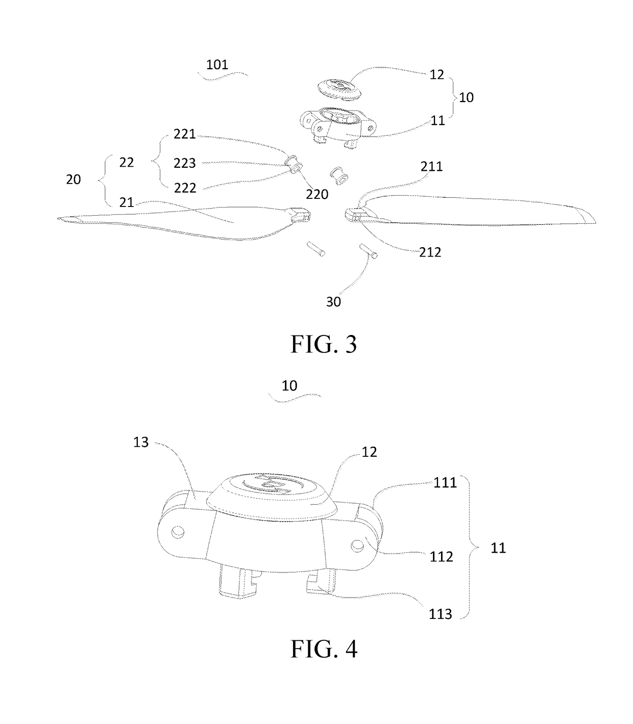
[0048]Referring to FIG. 1 and FIG. 2, FIG. 1 and FIG. 2 show a foldable propeller 101 according to an embodiment of the present application. The foldable propeller 101 includes: a propeller hub 10, two blade assemblies 20 and two connecting members 30. The propeller hub 10 is pivotally connected to the blade assemblies 20 through the connecting members 30. Each blade assembly 20 is rotatable with respect to the propeller hub 10, and a rotation axis 20a of each blade assembly 20 is perpendicular to an axial central line 10a of the propeller hub 10. The rotation axis 20a can be an axial central line of the connecting member 30. Therefore, in this embodiment of the present application, the blade assemblies 20 can be folded upward or downward with respect to the propeller hub 10.
[0049]In this embodiment, when the foldable propeller 101 is perpendicular to the ground and no external force is applied on the foldable propeller 101, as shown in FIG. 2, the blade assemblies 20 are folded dow...
embodiment 2
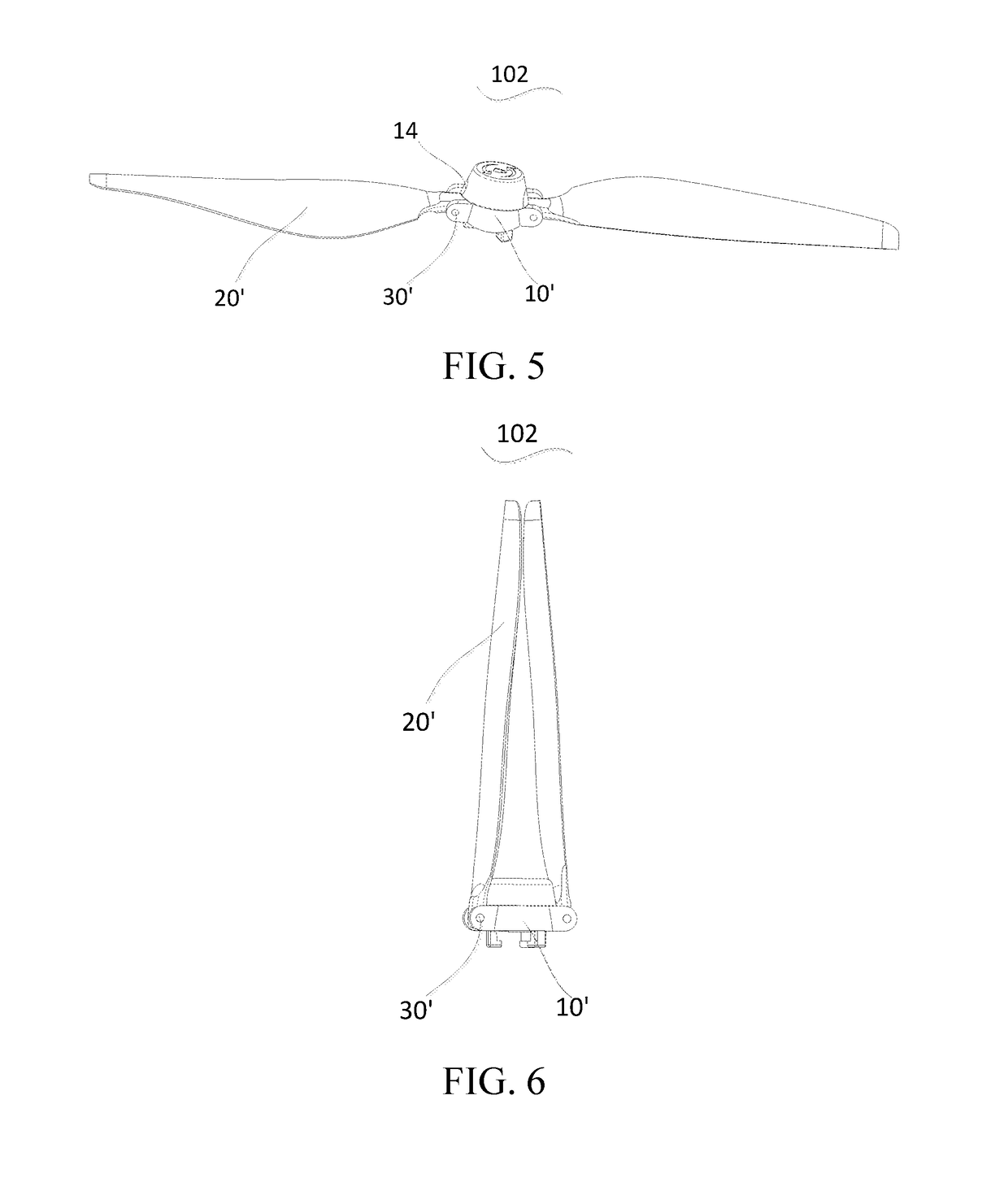
[0060]Referring to FIG. 5 to FIG. 7, FIG. 5 to FIG. 7 show another foldable propeller 102 according to an embodiment of the present application. The foldable propeller 102 is substantially the same as the foldable propeller 101 provided in Embodiment 1, and the difference lies in that: in this embodiment, the limiting stoppers 13 are omitted in the propeller hub 10, and the propeller hub 10 further includes limiting grooves 14 that are provided corresponding to the blade assemblies 20, and each limiting groove 14 keeps consistent with a root shape of the corresponding blade assembly 20.
[0061]In this embodiment, because the limiting stoppers 13 are removed, when the foldable propeller 102 does not work, the blade assemblies 20 can be folded upward with respect to the propeller hub 10 if a vertically upward force is exerted on the blade assemblies 20. The propeller hub 10 further includes limiting grooves that are provided corresponding to the blade assemblies 20, and each limiting gr...
embodiment 3
[0062]An embodiment of the present application further provides a power assembly 201. As shown in FIG. 8, the power assembly 201 includes a driving device 2011 and a foldable propeller 101 / 102 in either of the foregoing embodiments. The foldable propeller 101 / 102 is mounted on the driving device 2011, and the driving device 2011 drives the blade assemblies 20 of the foldable propeller 101 / 102 to rotate. The driving device 2011 may be a motor of any type. In addition, in FIG. 8, the power assembly 202 including the foldable propeller 101 is taken as an example for description, but it does not limit the embodiment of the present application.
[0063]In addition, it can be understood that the power assembly 201 provided in this embodiment includes the structure features and corresponding beneficial effects of the foldable propeller 101 / 102. For technical details that are not described in this embodiment, refer to Embodiment 1 and Embodiment 2.
PUM
 Abstract
Description
Claims
Application Information
 - R&D
- Intellectual Property
- Life Sciences
- Materials
- Tech Scout
- Unparalleled Data Quality
- Higher Quality Content
- 60% Fewer Hallucinations
Browse by: Latest US Patents, China's latest patents, Technical Efficacy Thesaurus, Application Domain, Technology Topic, Popular Technical Reports.
© 2025 PatSnap. All rights reserved.Legal|Privacy policy|Modern Slavery Act Transparency Statement|Sitemap|About US| Contact US: help@patsnap.com


