Mount structure
a technology of mounting structure and mounting plate, which is applied in the direction of machine supports, furniture parts, other domestic objects, etc., can solve the problems of increasing packing cost, increasing assembly and usage costs, and relatively low package utility, and enhancing structural strength of the package. , the effect of increasing packing cos
- Summary
- Abstract
- Description
- Claims
- Application Information
AI Technical Summary
Benefits of technology
Problems solved by technology
Method used
Image
Examples
first embodiment
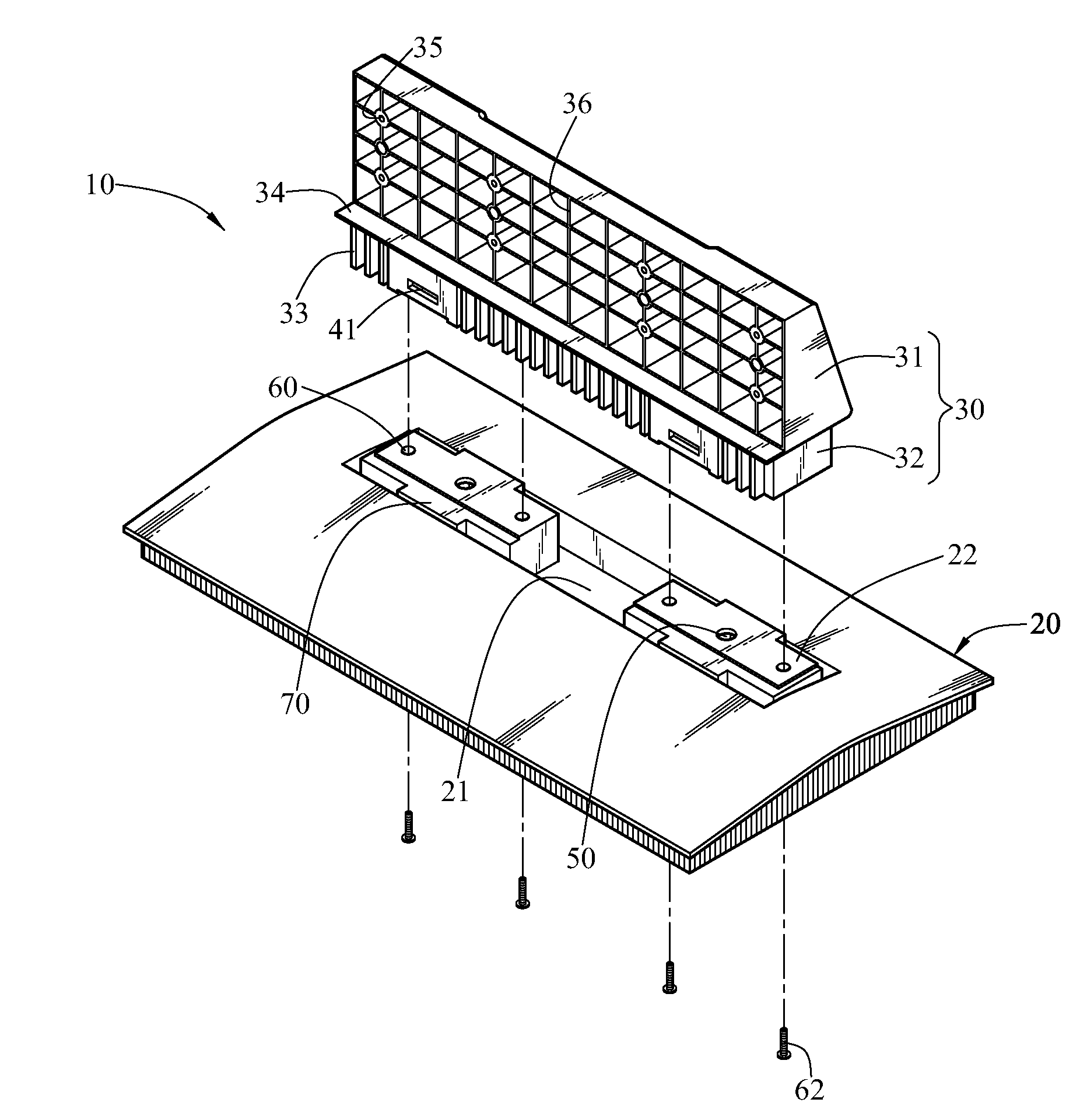
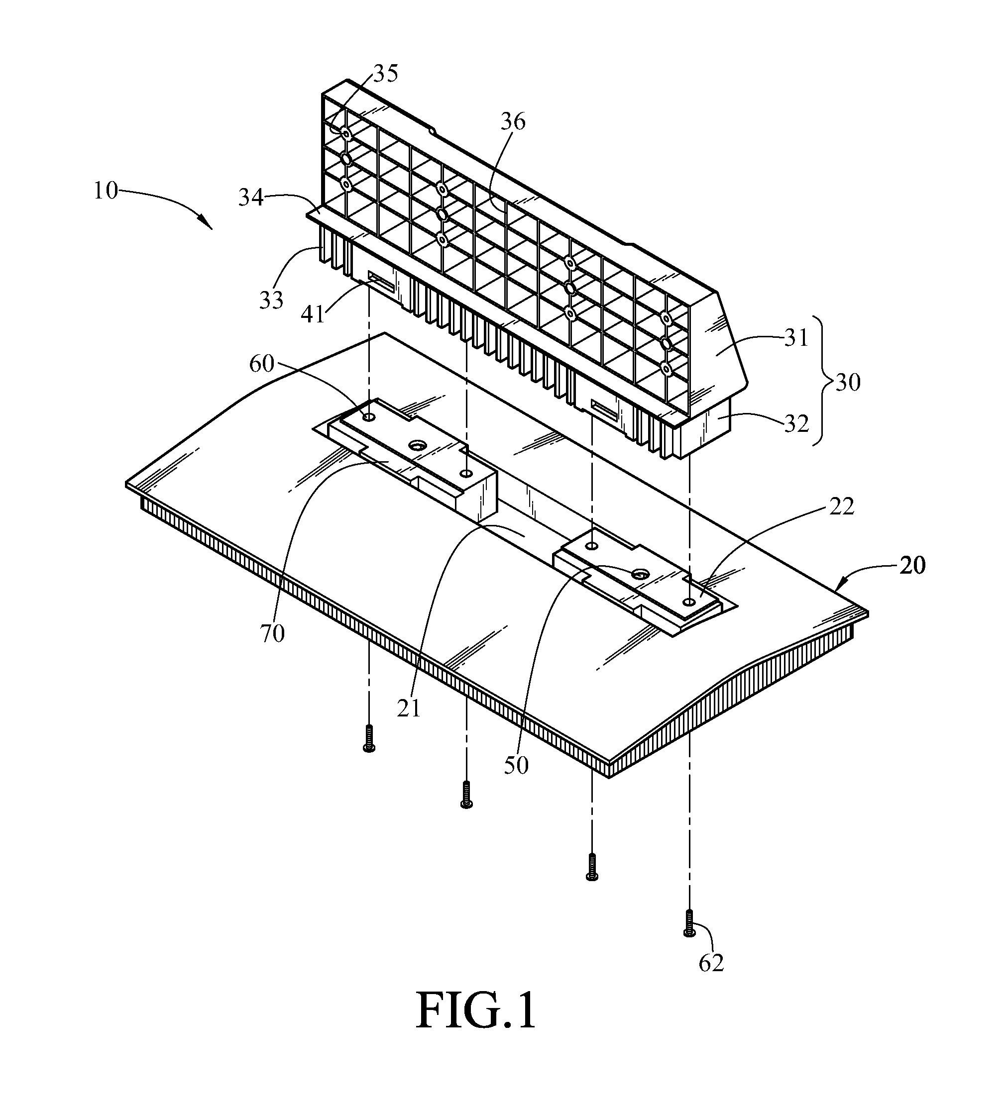
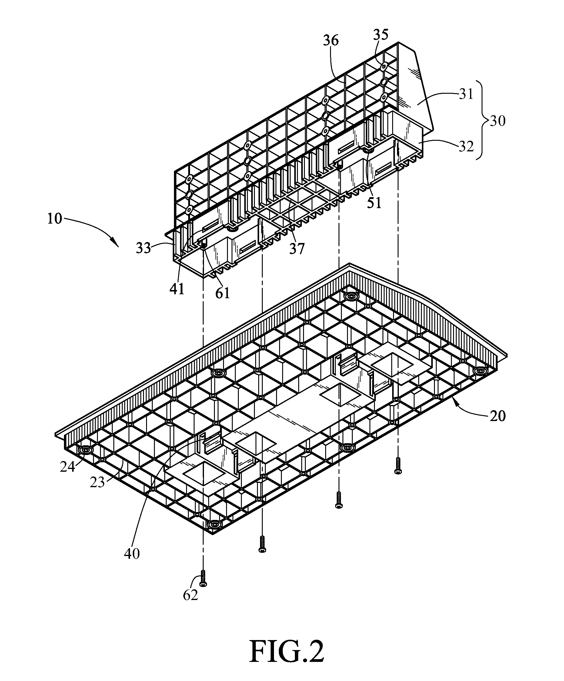
[0024]Referring to FIGS. 1 to 5, schematic views of the present invention are shown. A mount structure of the present invention includes a base 20 and a bearer 30.
[0025]The base 20 has a surface of a quasi-trapezoidal structure with a relatively higher central part and two lower sides. A slot 21 is opened on an upper surface of the base 20, and two combining blocks 22 are disposed on and protrudent from the slot 21. The bearer 30 has a bearing portion 31 and a combining portion 32, the bearing portion 31 is used for being combined to the display 11, and the combining portion 32 is used for being installed in the slot 21, such that the bearer 30 is stably installed on the base 20.
[0026]Suspending hooks 40 are respectively disposed on two sides of each combining block 22 corresponding to the combining portion 32. Buckle holes 41 with the same number as the hooks 40 are disposed on one side of the combining portion 32 opposite to the base 20 and corresponding to the hooks 40. When the ...
second embodiment
[0034]Referring to FIGS. 7 and 8, schematic views of the present invention are shown, in which symbols of FIGS. 1 to 4 are employed. A mount structure of the present invention includes a base 20 and a bearer 30. The base 20 has a surface of a quasi-trapezoidal structure with a relatively higher central part and two lower sides. A slot 21 is opened on an upper surface of the base 20, and two combining blocks 22 are disposed protruding from the slot 21. The bearer 30 has a bearing portion 31 and a combining portion 32, the bearing portion 31 is used for being combined to the display 11 (referring to FIG. 5), and the combining portion 32 is used for being installed in the slot 21, such that the bearer 30 is stably installed on the base 20. Suspending hooks 40 are respectively disposed on two sides of the combining block 22 corresponding to the combining portion 32, and buckle holes 41 with the same number as the hooks 40 are disposed on one side of the combining portion 32 opposite to ...
third embodiment
[0037]Referring to FIG. 9, a schematic view of the present invention is shown, in which numerals of FIGS. 1 to 4 are employed. A mount structure of the present invention includes a base 20 and a bearer 30. A slot 21 (referring to FIG. 1) is opened on an upper surface of the base 20, and two combining blocks 22 (referring to FIG. 1) are disposed protruding from the slot 21. The bearer 30 has a bearing portion 31 and a combining portion 32, the bearing portion 31 is used for being combined to the display 11 (referring to FIG. 5), and the combining portion 32 is used for being installed in the slot 21, such that the bearer 30 is stably installed on the base 20. Buckle holes 41 are respectively disposed on two sides of each combining block 22 corresponding to the combining portion 32, and hooks 40 with the same number as the buckle holes 41 are disposed on one side of the combining portion 32 opposite to the base 20 and corresponding to the buckle holes 41. When the combining portion 32...
PUM
 Abstract
Description
Claims
Application Information
 - R&D
- Intellectual Property
- Life Sciences
- Materials
- Tech Scout
- Unparalleled Data Quality
- Higher Quality Content
- 60% Fewer Hallucinations
Browse by: Latest US Patents, China's latest patents, Technical Efficacy Thesaurus, Application Domain, Technology Topic, Popular Technical Reports.
© 2025 PatSnap. All rights reserved.Legal|Privacy policy|Modern Slavery Act Transparency Statement|Sitemap|About US| Contact US: help@patsnap.com


