
Surgical microscopy system having an optical coherence tomography facility

a technology of optical coherence tomography and surgical microscope, which is applied in the field of surgical microscope system having optical coherence tomography (oct) facility, to achieve the effect of increasing the dynamic range of the system for wavefront measuremen

Active Publication Date: 2011-11-01
CARL ZEISS MEDITEC INC
View PDF57 Cites 77 Cited by
  • Summary
  • Abstract
  • Description
  • Claims
  • Application Information

AI Technical Summary

Benefits of technology

The present invention provides a surgical microscopy system with an optical coherence tomography (OCT) facility. The system includes microscopy optics for generating an image of a first object region and an OCT system with an OCT beam path. The microscopy optics have an objective lens and are designed for stereoscopic optical imaging. The OCT system has an OCT beam scanner and a reflector that reflects the OCT-measuring light onto the first object region. The imaging optics are designed to guide the light rays emanating from the second object region to the image region, which is located near the reflector. The system also includes collimating optics and a beam scanner. The position of the reflector and the distance between the beam scanner and the second object region can be adjusted based on requirements of the application. The technical effects of the invention include improved visualization of the surgical field and reduced vignetting of microscopy light.

Problems solved by technology

However, in this system it is difficult to arrange a reflector which deflects the OCT-measuring light beam of the OCT system in order to guide it to and traverse the objective lens of the optical microscopy system, thus to be incident on the object without impairing the performance of the optical microscopy system.

Method used


Image

  • Surgical microscopy system having an optical coherence tomography facility
  • Surgical microscopy system having an optical coherence tomography facility
  • Surgical microscopy system having an optical coherence tomography facility

Examples


Embodiment Construction

[0056]In the exemplary embodiments described below, components that are alike in function and structure are designated as far as possible by alike reference numerals. Therefore, to understand the features of the individual components of a specific embodiment, the descriptions of other embodiments and of the summary of the invention should be referred to.

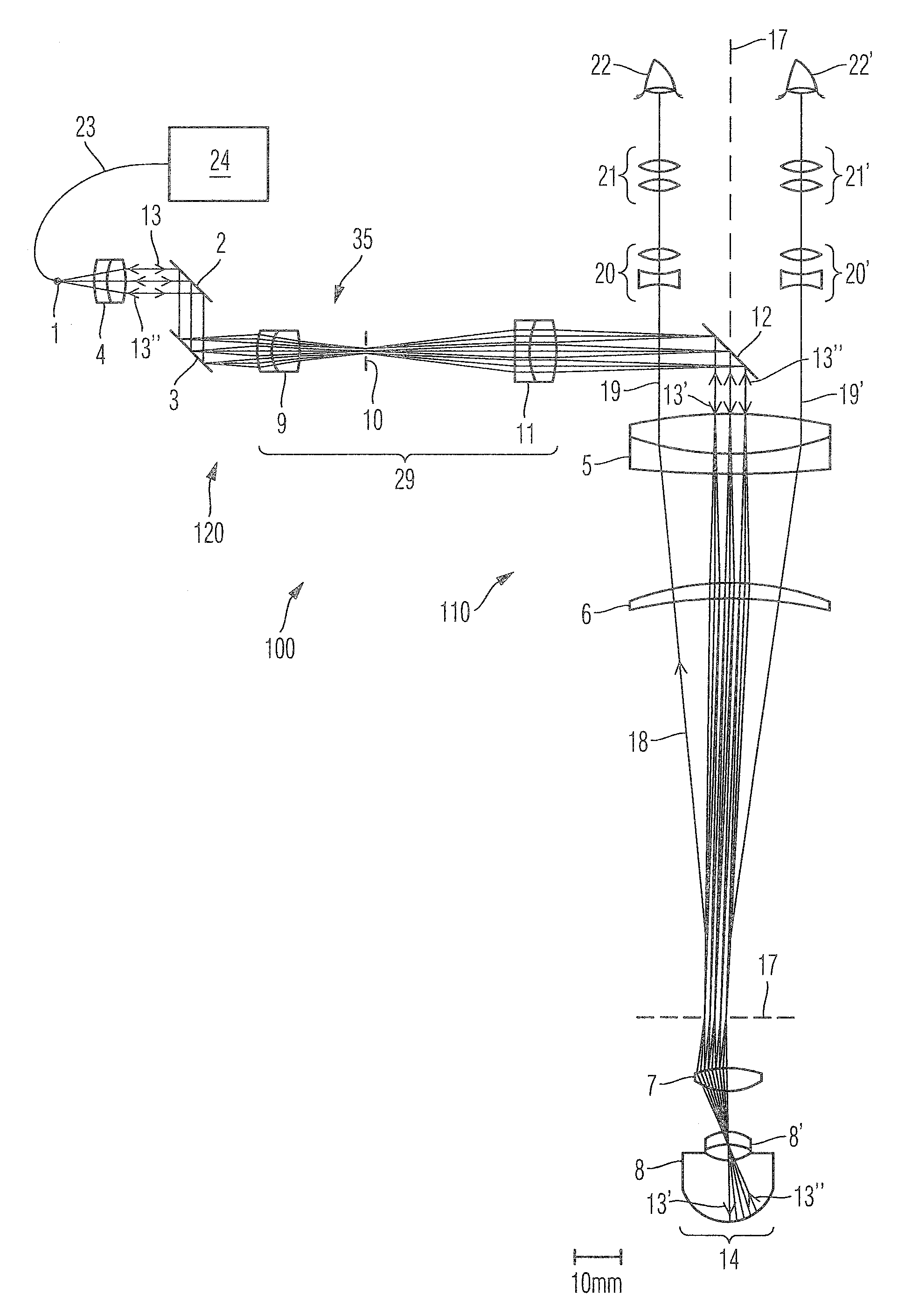
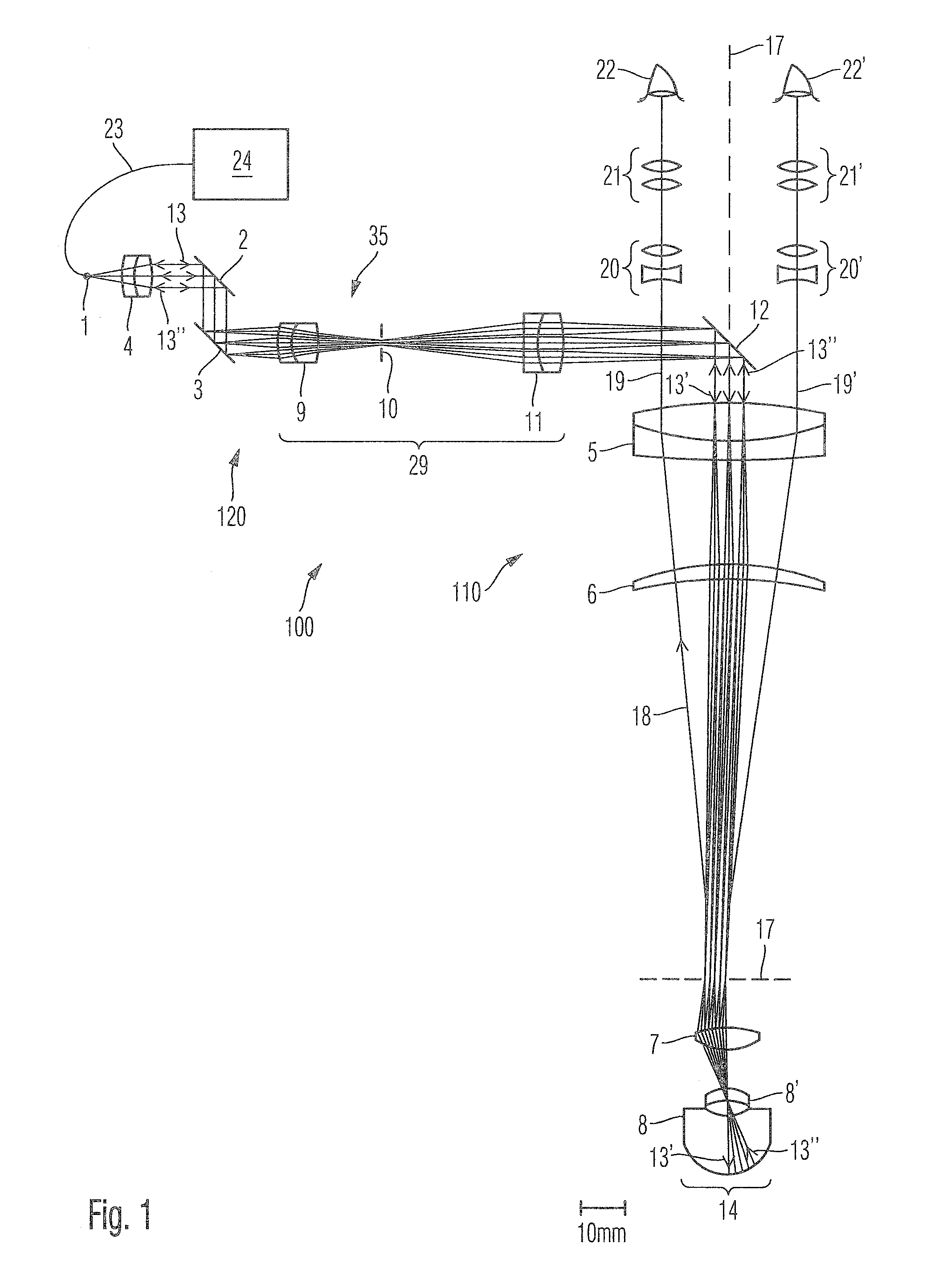
[0057]FIG. 1 schematically illustrates a surgical microscopy system 100 according to the present invention. The surgical microscopy system 100 is comprised of microscopy optics 110 and an OCT system 120.

[0058]The microscopy optics 110 images a first object region 14, in this case a retina of a patient's eye 8, to a retina of a left eye 22a and a retina of a right eye 22b of a user of the microscopy system. For this purpose, the patient's eye 8 is illuminated with illumination light generated by a not illustrated illumination light source. Depending on the application, the illumination light source may be a xenon light source or a hal...


PUM

PropertyMeasurementUnit
distancesaaaaaaaaaa
wavelengthaaaaaaaaaa

Abstract

A surgical microscopy system is provided wherein an optical coherence tomography facility is integrated into a microscopy system. A beam of measuring light formed by collimating optics of an OCT system is deflected by a beam scanner, traverses imaging optics, and is reflected by a reflector such that the beam of measuring light traverses an objective lens of microscopy optics and is directed to an object region of the microscopy optics. A position of the beam of measuring light being incident on the reflector is substantially independent on a direction into which the beam of measuring light is deflected by the beam scanner. When traveling through the beam scanner, the beam of measuring light is comprised of a bundle of substantially parallel light rays.

Description

CROSS-REFERENCES TO RELATED APPLICATIONS[0001]This present application claims priority to U.S. Provisional Patent Application No. 61 / 070,197, filed on Mar. 19, 2008, the disclosure of which is hereby incorporated by reference in its entirety for all purposes.BACKGROUND OF THE INVENTION[0002]The present invention relates to a surgical microscopy system having an optical coherence tomography (OCT) facility. In particular, the present invention relates to a surgical microscopy system having an OCT facility, wherein a beam of measuring light is scanned across an object to be analyzed by the OCT facility.[0003]An OCT system is for example known from EP 0 697 611 A2. A broad-band OCT-light source generates OCT-measuring light comprising different wavelengths within a certain bandwidth. A principal wavelength generated by the OCT-light source and the bandwidth of the OCT-light source determine the coherence length of the OCT-measuring light. There is a reciprocal relationship between the b...

Claims


Application Information

Patent Timeline
Patent Type & Authority Patents(United States)
IPC IPC(8): G01B11/02G01N21/00
CPCA61B3/102A61B3/13A61B19/5223G01N21/4795G02B21/0012G02B21/082G02B21/22A61B90/20
Inventor HAUGER, CHRISTOPHSEESSELBERG, MARKUSO'HARA, KEITHQIU, YUEWEI, XINGHORN, JOCHEN M.REIMER, PETER
Owner CARL ZEISS MEDITEC INC
Learn More