Tent rafter end cap and tent incorporating same

a technology of tent frame and end cap, which is applied in the field of tents, can solve the problems of uneven bottom surfaces, and achieve the effect of reducing or avoiding the damage of fabric panels due to blemishes in structural members

Inactive Publication Date: 2011-11-08
JOHNSON OUTDOORS
View PDF16 Cites 13 Cited by
  • Summary
  • Abstract
  • Description
  • Claims
  • Application Information

AI Technical Summary

Benefits of technology

[0014]A method of assembling a tent is also provided in one implementation of the invention. The method includes the following steps: 1) positioning an end cap adjacent an end of a tent rafter having a fabric mounting channel; 2) feeding an edge portion of the fabric panel through the fabric mounting channel, starting the feeding at the end of the tent rafter; 3) supporting at least a portion of the weight of the portion of the fabric panel that is not fed through the fabric mounting channel or resting on the ground by the end cap. This method removes the weight of the suspended, i.e. vertically draping, portion of the fabric panel from the structural member, i.e. rafter, during assembly. As such, damage to the fabric panel due to blemishes in the structural member can be reduced or avoided. Thus, in one implementation, the method includes the step of providing the majority of the non-vertical lateral support for the fabric panel by the tent rafter and not the end cap.

Problems solved by technology

However in alternative embodiments, the bottom surfaces may not align.

Method used


Image

  • Tent rafter end cap and tent incorporating same
  • Tent rafter end cap and tent incorporating same
  • Tent rafter end cap and tent incorporating same

Examples


Embodiment Construction

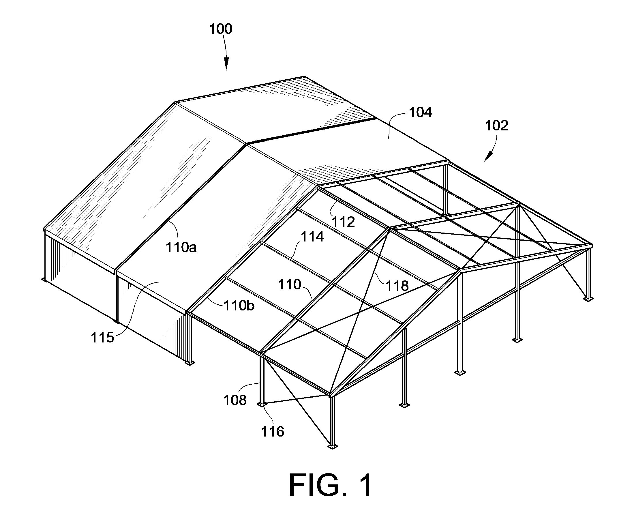
[0032]FIG. 1 illustrates a partial illustration of a typical tent 100 including structural members in accordance with the teachings of the present invention. The tent 100 includes a tent frame 102 that supports a shell 104 to provide a shelter or building like structure.

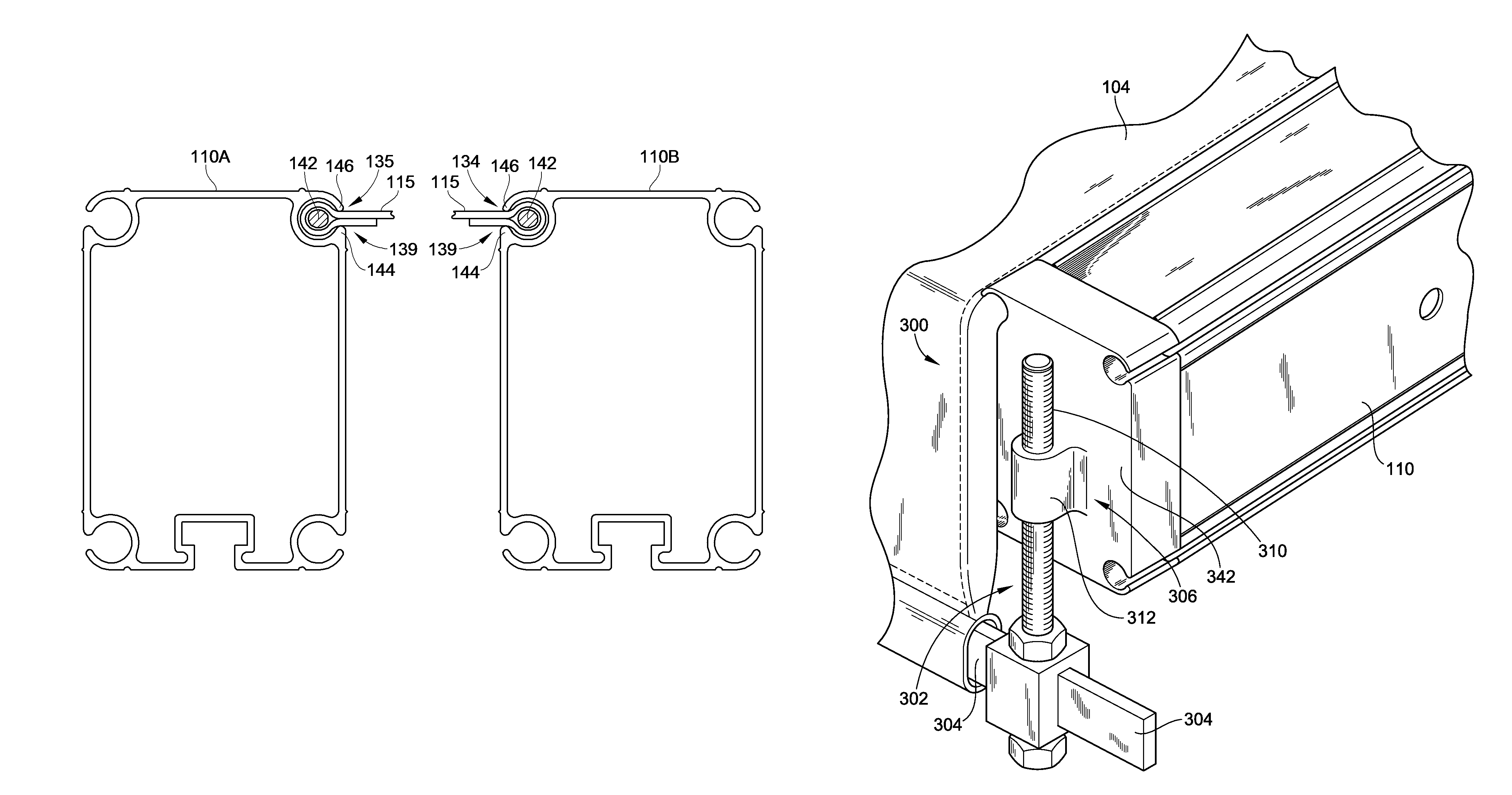
[0033]The tent frame 102 is generally constructed of a plurality of structural members including a plurality of legs 108 that generally define the vertical walls of the tent, a plurality of rafters 110 that extend at an angle relative to the legs 108 and that meet at the peak 112 of the tent 100 and a plurality of purlins 114 that extend horizontally between the rafters 110 and generally parallel to the peak 112. Typically, purlins 114 are made of smaller profiles. The peak 112 is formed by purlins 114. Purlins in this position are also referred to as ridge purlins. The illustrated tent frame 102, is a clear span tent frame that is free of interior poles.

[0034]The legs 108 are mounted to feet 116 which rest on the gr...


PUM


Abstract

A tent including a structural member and an end cap insertable into the structural member and a method of forming a tent are provided. The structural member is preferably a rafter. The rafter has C-channels aligned with support troughs of the end cap. The C-channels and support troughs receive edge portions of a fabric panel therein to secure the fabric panel to the rafter. The end cap supports the weight of the fabric panel during assembly to reduce or avoid engagement of the fabric panel with corners of the C-channel or burs formed in the end of the C-channel of the rafter as the fabric panel is fed through the C-channel. The end cap may also include an optional tension push down bar assembly for providing additional tensioning of the fabric panel.

Description

CROSS-REFERENCE TO RELATED PATENT APPLICATIONS[0001]This patent application claims the benefit of U.S. Provisional Patent Application No. 61 / 037,155, filed Mar. 17, 2008, the entire teachings and disclosure of which are incorporated herein by reference thereto.FIELD OF THE INVENTION[0002]This invention generally relates to tents and more particularly to tent frames and structural members of tent frames.BACKGROUND OF THE INVENTION[0003]A tent can be very large and can be used for providing a shelter and environment for large gatherings and celebrations such as, for example, concerts, theatrical events, wedding receptions and conventions. The tent generally includes a shell, formed from one or more fabric panels, that is supported by a frame made of numerous structural members. The structural members may include vertical legs that define the walls and rafters that extend at an angle relative to the vertical legs and toward a peak of the tent to define the roof.[0004]Many of the struct...

Claims


Application Information

Patent Timeline
Patent Type & Authority Patents(United States)
IPC IPC(8): E04H15/32
CPCE04H15/18E04H15/644Y10S135/909Y10S135/907
Inventor WHITLOW, ANTHONY
Owner JOHNSON OUTDOORS
Why Eureka
Try Eureka