Peristaltic pump

a peristaltic pump and peristaltic technology, applied in the direction of machines/engines, flexible member pumps, positive displacement liquid engines, etc., can solve the problems of requiring periodic replacement, tubing tends to deteriorate, and little, if any, opportunity for fluid contamination, so as to improve the service life and the effect of durable and convenient peristalti

Inactive Publication Date: 2011-11-08
BECHER JAMES J
View PDF10 Cites 3 Cited by
  • Summary
  • Abstract
  • Description
  • Claims
  • Application Information

AI Technical Summary

Benefits of technology

[0004]It is therefore an object of the present invention to provide for an improved durable and easy to service peristaltic pump, which utilizes a long-lasting pump tube that requires infrequent maintenance and replacement.

Problems solved by technology

Because the pump fluid is contained completely within the tubing, there is little, if any, opportunity for the fluid to be contaminated.
Such tubing tends to deteriorate after prolonged use and requires periodic replacement.
In either case, the tubing must be tediously reattached to the pump by the aforesaid clamps or brackets.
This tends to be a time consuming, annoying and inconvenient procedure that prolongs the pump's downtime.

Method used


Image

  • Peristaltic pump
  • Peristaltic pump
  • Peristaltic pump

Examples


Embodiment Construction

[0014]Other objects, features and advantages will occur from the following description of a preferred embodiment and the accompanying drawings, in which:

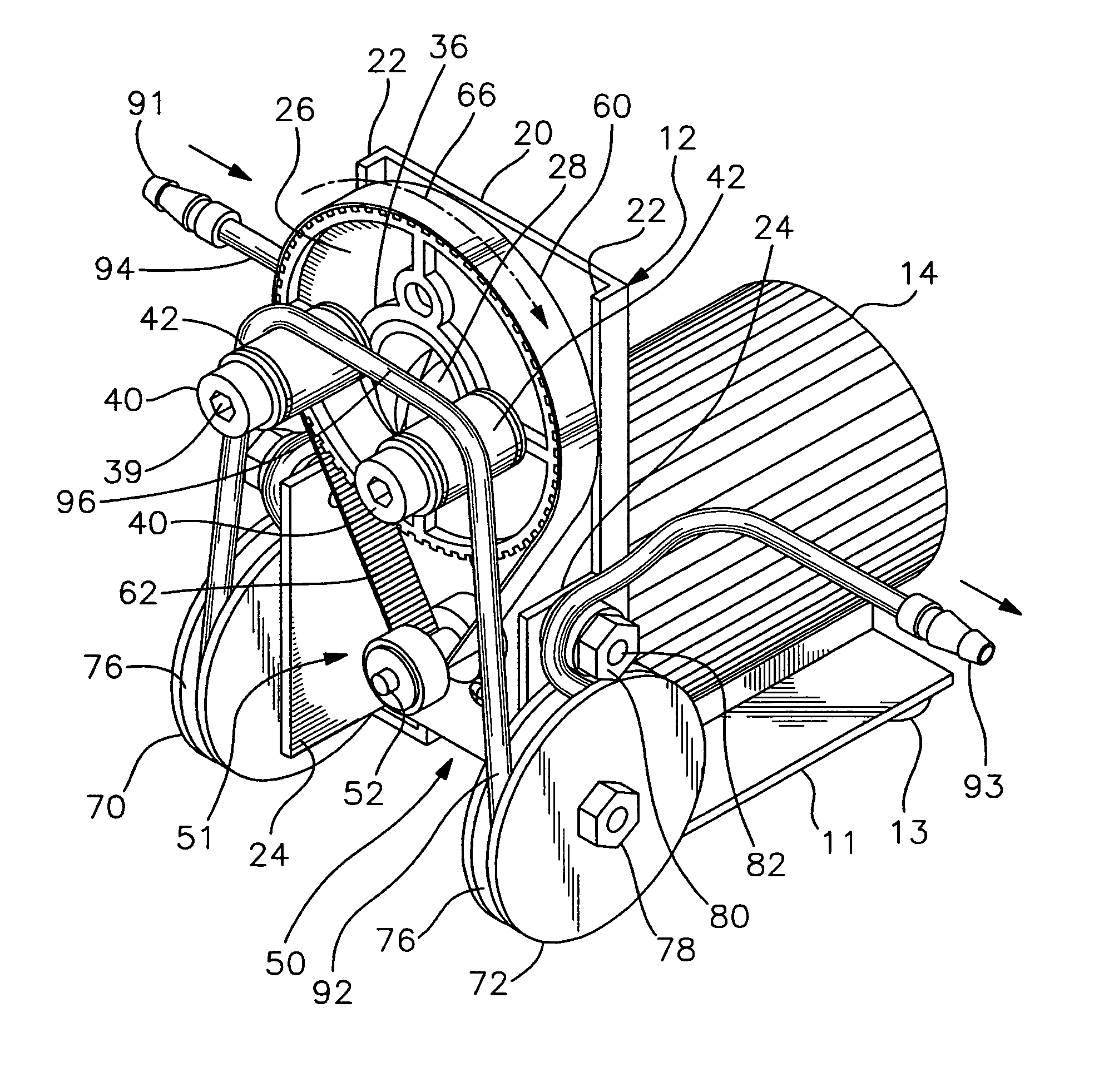
[0015]FIG. 1 is a perspective view of a low volume peristaltic pump according to this invention;

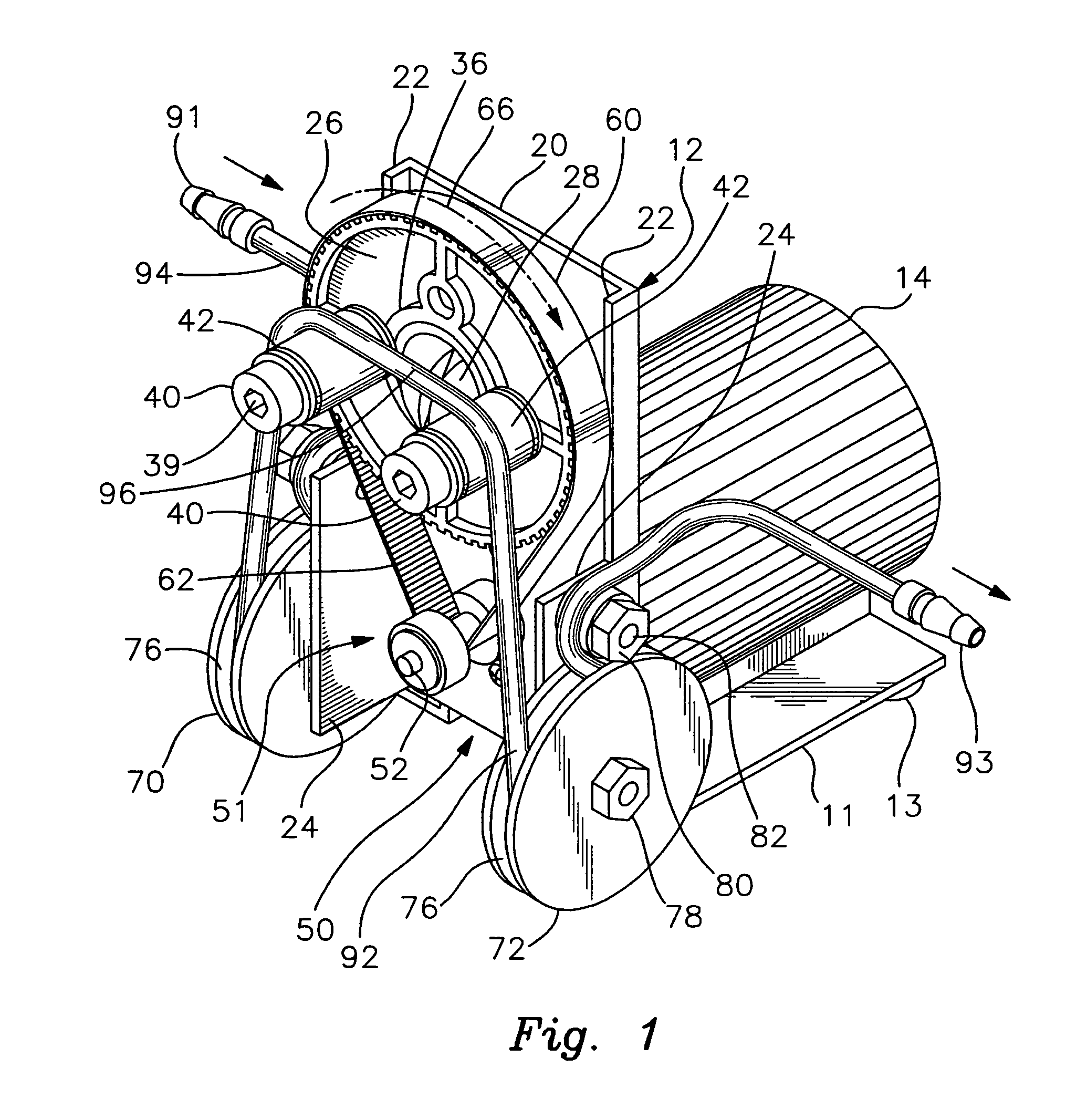
[0016]FIG. 2 is a side elevational view of the peristaltic pump;

[0017]FIGS. 3 and 4 are front elevational views of the pump depicting sequential rotation of the rotor and corresponding operation of the pump such that fluid is moved through the resilient tubing;

[0018]FIG. 5 is a rear elevational view of the peristaltic pump; and

[0019]FIG. 6 is a perspective view of the pump with the tube shown in fragmentary fashion and disengaged from the mounting sheaves.

[0020]There is shown in FIGS. 1-6 a low volume peristaltic pump 10 that is designed for pumping liquids in various applications. Pump 10 may be used for a wide variety of industrial uses, such as in the chemical water treatment, mining and other industries. The particular technology, app...


PUM


Abstract

A peristaltic pump includes a support section and a rotor mounted for rotation on the support section. There are a pair of spaced apart cam elements attached to and extending from the rotor. A drive mechanism rotatably operates the rotor such that the cam elements are turned together with the rotor. There are first and second mounting sheaves connected to the support section. Each mounting sheave has a groove formed peripherally therein. An elongate, resilient tube conducts liquid therethrough. The tube includes leading and trailing tube segments and an intermediate tube segment formed longitudinally therebetween. The leading segment is retainably inserted in the groove of the first sheave and the trailing segment is retainably inserted in the groove of the second sheave to hold the intermediate segment of the tube for being operatively engaged by the cam elements as the rotor is operated. This causes liquid to be pumped peristaltically through the intermediate segment of the tube from the trailing segment to the leading segment.

Description

FIELD OF THE INVENTION[0001]This invention relates to an improved peristaltic pump and, in particular, to a peristaltic pump utilizing a resiliently flexible fluid conducting tube that is releasably attached to a pair of “quick connect” mounting sheaves.BACKGROUND OF THE INVENTION[0002]Low volume peristaltic pumps are currently utilized in a wide variety of industrial applications (e.g. water treatment, mining, chemical processing) where abrasive, corrosive and / or viscous liquids must be pumped. Such pumps employ the principal of peristalsis to deliver the fluid through a flexible tube or hose. Peristaltic pumps have no valves or seals and the pump fluid contacts only the interior of the tube. As a result, the pump is fairly easy to clean and sterilize. Even caustic and / or abrasive fluids exert little wear and tear on the pump parts so that maintenance is simplified considerably. By the same token, the gentle pumping action exhibited by the peristaltic pump causes little, if any, da...

Claims


Application Information

Patent Timeline
Patent Type & Authority Patents(United States)
IPC IPC(8): F04B45/08
CPCF04B43/1215F04B43/1261F04B45/08
Inventor BECHER, JAMES J.
Owner BECHER JAMES J
Why Eureka
Try Eureka