Apparatus for monitoring of brushes, in particular slipring or commutator brushes, on electrical machines

a technology for electrical machines and brushes, applied in the direction of motor/generator/converter stoppers, dynamo-electric converter control, instruments, etc., can solve the problems of large potential danger, easy to overlook indications, and inability to monitor so easily by maintenance personnel

Inactive Publication Date: 2011-11-08
GENERAL ELECTRIC TECH GMBH
View PDF10 Cites 14 Cited by
  • Summary
  • Abstract
  • Description
  • Claims
  • Application Information

AI Technical Summary

Benefits of technology

[0022]at least one electronic sensor configured to be arranged in or on the brush apparatus and to locally draw electrical supply power directly from the electromagnetic environment of the brush apparatus, and to transmit detected measurement data by means of electromagnetic radiation. In an apparatus such as this, there is therefore no need for an electrically conductive signal or connecting lines to the sensor for remote monitoring of a brush in the brush apparatus, as a result of which the potential hazard resulting from the high electrical voltages and potentials which generally occur in electrical machines can be reduced considerably in comparison to remote monitoring solutions in which electrical signal or connecting lines are used. In this case, the expression “brush apparatus” means in particular not only a pure brush, such as a slipring or commutator brush, but also a brush together with a brush housing.

Problems solved by technology

These brushes can be manufactured from carbon and graphite materials and are subject to relatively high wear.
However, in these known apparatuses, in some cases, only a local indication of the fault state, that is to say of a worn-out brush, is provided.
Since the brush apparatuses of electrical machines can be in a closed form, this indication can easily be overlooked, or cannot be monitored so easily by maintenance personnel.
Because of the generally high electrical voltage and the high potential energies which exist in electrical machines, for example in the case of an electrical generator, when in the energized state, this results, however, in a major potential danger.
Measures to cope with this potential change are generally quite complex.

Method used


Image

  • Apparatus for monitoring of brushes, in particular slipring or commutator brushes, on electrical machines
  • Apparatus for monitoring of brushes, in particular slipring or commutator brushes, on electrical machines
  • Apparatus for monitoring of brushes, in particular slipring or commutator brushes, on electrical machines

Examples


Embodiment Construction

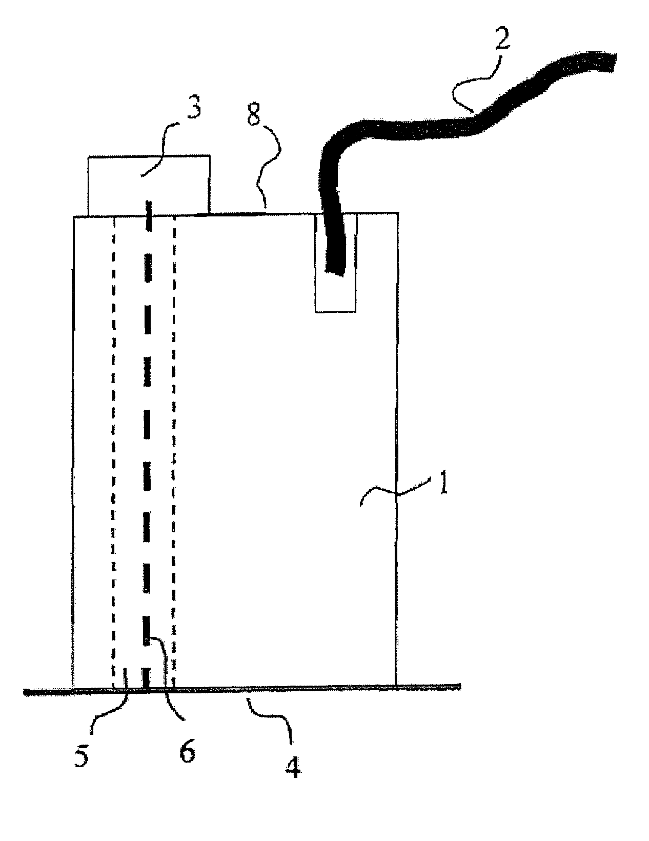
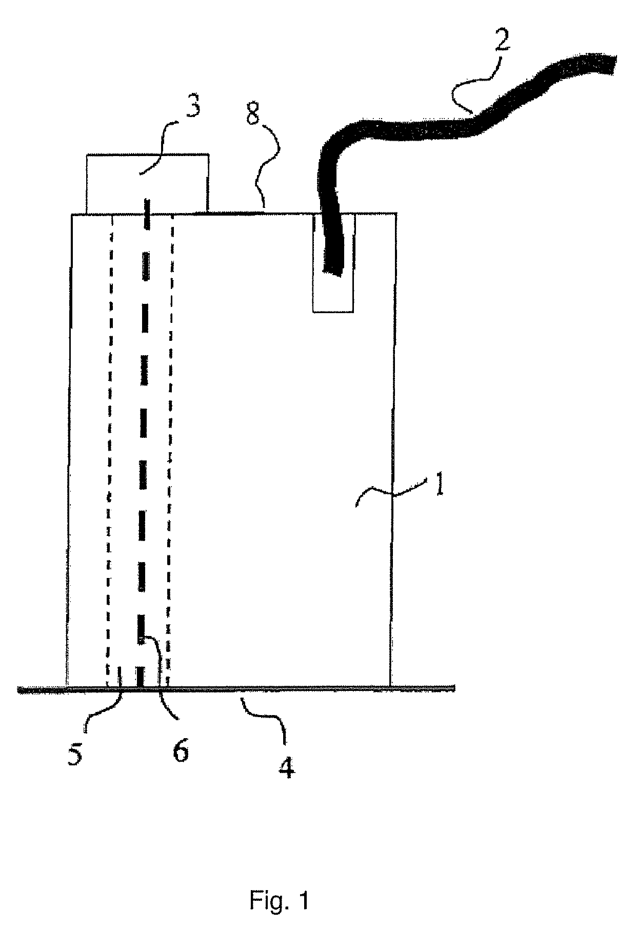
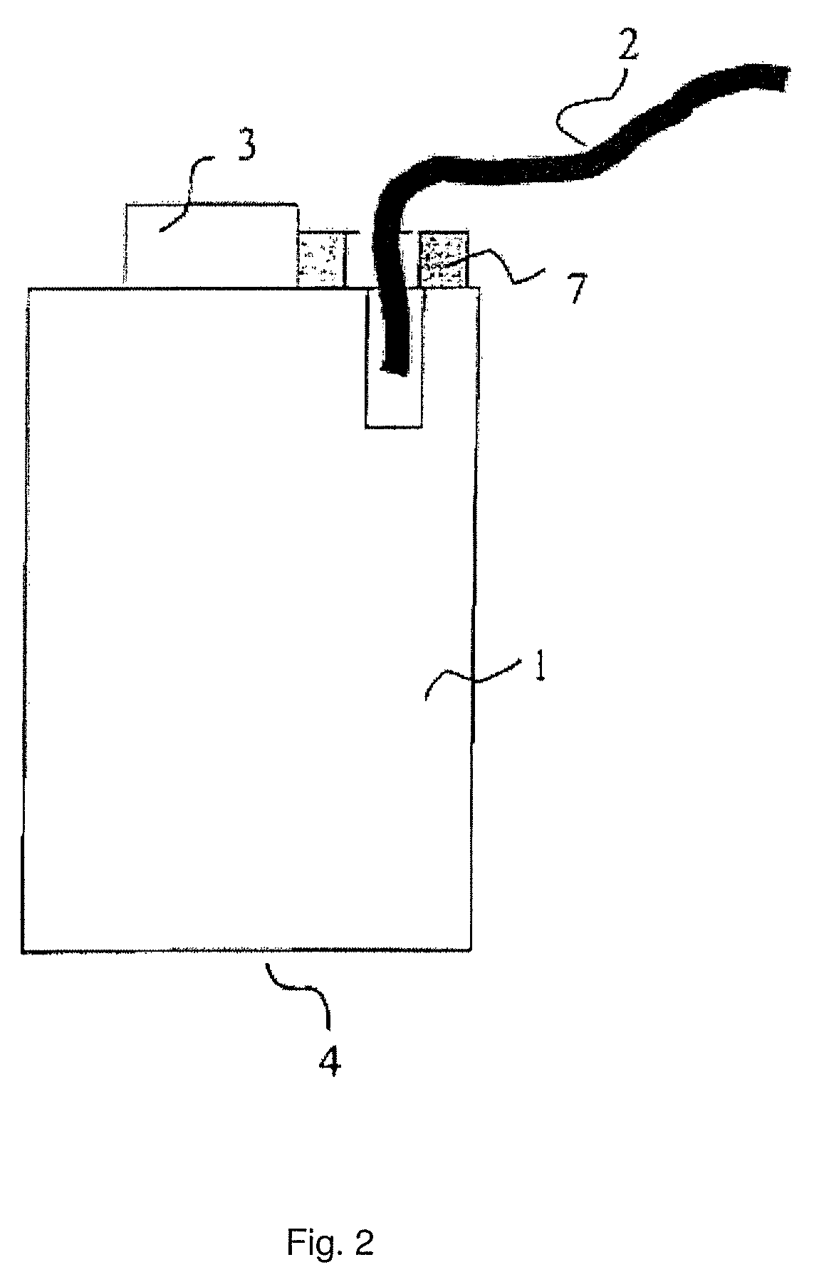
[0015]An apparatus is disclosed for monitoring of brushes, such as slipring or commutator brushes, on electrical machines which can allow safe continuous remote monitoring of a brush.

[0016]In an exemplary embodiment, an electronic sensor is configured to be arranged in or on the brush apparatus of an electrical machine, which electronic sensor locally draws its supply power directly from an electromagnetic environment of the brush apparatus and transmits detected measurement data by means of electromagnetic radiation, that is to say without using electrical signal or connecting lines. One exemplary principle of the disclosure is, inter alia, the knowledge that, in principle, voltage sources are already available for supplying power to the electronic sensor in the brush apparatus.

[0017]On the one hand, according to an exemplary embodiment of the disclosure, the voltage drop across a brush can be used to supply voltage to the sensor. On the other hand, according to another embodiment ...


PUM


Abstract

An apparatus is disclosed for monitoring brushes, such as slipring or commutator brushes, on electrical machines. At least one electronic sensor is configured to be arranged in or on a brush apparatus of an electrical machine such that an electrical supply power can be locally drawn directly from an electromagnetic environment of the brush apparatus. The apparatus can transmit measurement data detected by it by electromagnetic radiation to an indication device.

Description

RELATED APPLICATION[0001]This application claims priority under 35 U.S.C. §119 to German Patent Application No. 10 2007055795.9 filed in Germany on Dec. 13, 2007, the entire content of which is hereby incorporated by reference in its entirety.TECHNICAL FIELD[0002]An apparatus for monitoring of brushes is disclosed, such as slipring or commutator brushes, on electrical machines such as generators.BACKGROUND INFORMATION[0003]Large electrical generators or motors can include sliprings or commutators and associated brushes, via which the field current or drive current is supplied. These brushes can be manufactured from carbon and graphite materials and are subject to relatively high wear. For smooth operation of an electrical machine with brushes such as these, it is desirable to monitor the brushes, in particular the brush wear, as continuously as possible.[0004]U.S. Pat. Nos. 4,950,933 and 4,739,208 have disclosed apparatuses in order to monitor the length of slipring brushes for a pr...

Claims


Application Information

Patent Timeline
Patent Type & Authority Patents(United States)
IPC IPC(8): G08B21/00
CPCH01R39/58H02K5/14H02K11/25H02K11/35
Inventor HOBELSBERGER, MAX
Owner GENERAL ELECTRIC TECH GMBH
Why Eureka
Try Eureka