Plug-in unit-mounting structure and electronic apparatus

a technology of unit mounting and electronic equipment, applied in the direction of electrical apparatus construction details, instruments, optical elements, etc., can solve the problems of difficult mounting of piu on metal shelves, different printed circuit boards in the direction of increasing in size, and existing guide rails not being suitable for mounting, etc., to achieve efficient housing of plug-in units

Inactive Publication Date: 2011-11-08
FUJITSU LTD
View PDF17 Cites 12 Cited by
  • Summary
  • Abstract
  • Description
  • Claims
  • Application Information

AI Technical Summary

Benefits of technology

[0020]The present invention has been made in view of the above-described problems, and an object thereof is to provide a plug-in unit-mounting structure which makes it possible to efficiently accommodate plug-in units without being dependent on the structure of a shelf.
[0021]Another object of the invention is to provide an electronic apparatus in which plug-in units that can be mounted in slots of shelves have a high freedom of design in changing the design thereof.
[0022]To attain the above object, there is provided a plug-in unit-mounting structure for mounting plug-in units having various circuit packages mounted on printed circuit boards thereof. The plug-in unit-mounting structure comprises a shelf that has connectors disposed on a back wiring board, for being fitted to the plug-in units, and at least one mounting frame that is mounted in the shelf, for each accommodating an associated one of the plug-in units, and enabling the plug-in unit to be inserted in and removed from an associated one of the connectors, the mounting frame being provided with a guide rail which enables a position of disposition of the plug-in unit to be changed according to a size of the plug-in unit.

Problems solved by technology

Therefore, in the cases of the metal shelves 100 and 300, there is a problem that existing guide rails are not suitable for the mounting of a PIU on which is mounted a different printed circuit board increased in size in the direction of thickness thereof and having a larger amount of wiring.
Further, in the case of the metal shelf 300 shown in FIG. 15, if a PIU has a different thickness, as in the case of a PIU in which a heat sink provided with a radiation fin is arranged on a printed circuit board, it is not easy to mount the PIU on the metal shelf 300.
As described above, the above-described electronic apparatuses suffer from the problem that it is not easy to replace PIUs mounted on a shelf or increase or reduce the number of mounting frames e.g. when changing the design of the apparatuses.

Method used


Image

  • Plug-in unit-mounting structure and electronic apparatus
  • Plug-in unit-mounting structure and electronic apparatus
  • Plug-in unit-mounting structure and electronic apparatus

Examples


first embodiment

[0048]A description will be given of a first embodiment of the present invention. The first embodiment will be described by taking an example of a plug-in unit-mounting structure in the light of the above-described outline. It should be noted that all PIUs according to the first embodiment are equal in width, and the width is defined as “the single-size width” (length in a direction orthogonal to the height and length of a PIU in the mounted state).

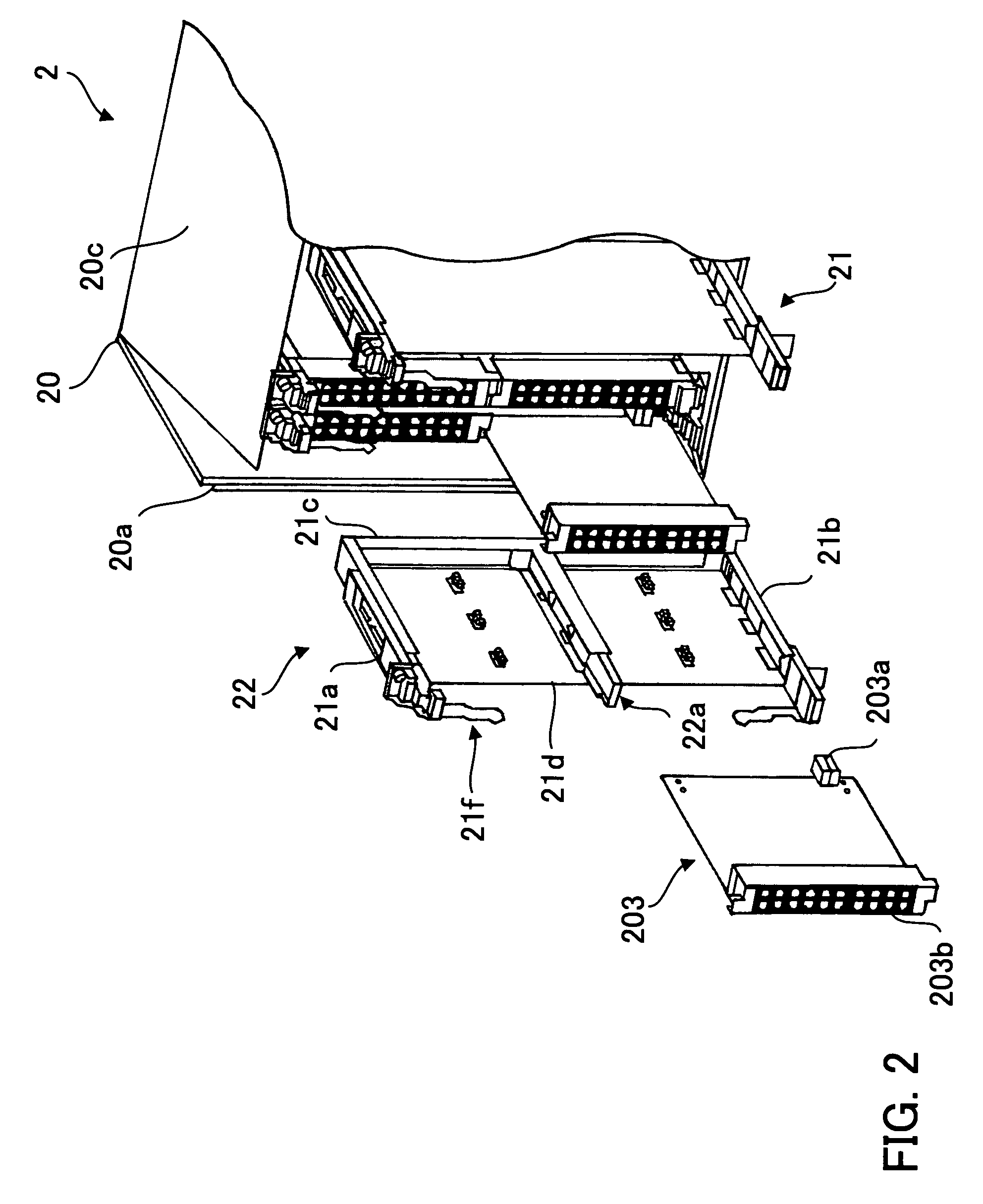
[0049]FIG. 2 is a schematic perspective view of the plug-in unit-mounting structure according to the first embodiment of the present invention.

[0050]In this plug-in unit-mounting structure 2, connectors (not shown) which can be fitted to the PIUs are disposed on a BWB (not shown) of a metal shelf 20, and mounting frames 21 and 22 adapted to various PIUs are accommodated side by side in the longitudinal direction of the metal shelf 20 in a predetermined arrangement.

[0051]The mounting frames 21 and 22 each include a vertical frame part 21c ...

second embodiment

[0062]In the first embodiment, the width of the PIU accommodated in the metal shelf is assumed to be the single-size width. In contrast, a second embodiment of the present invention will be described by taking an example of a case where a mounting frame is used which is capable of being adapted to both the single-size width and a double-size width which is twice as large as the single-size width. It should be noted that a metal shelf of a plug-in unit-mounting structure according to the second embodiment is identical to that of the plug-in unit-mounting structure according to the first embodiment, so that the description thereof is omitted.

[0063]FIG. 6 is a schematic perspective view of the mounting frame of the plug-in unit-mounting structure according to the second embodiment.

[0064]As described above, a mounting frame 32 includes a vertical frame part 31c to be pushed in toward the BWB, an upper frame part 31a and a lower frame part 31b which are horizontally fixed to upper and lo...

third embodiment

[0069]In a third embodiment of the present invention, a description will be given by taking as an example a case in which a mounting frame can be divided and the height thereof is made small.

[0070]FIG. 8 is a schematic perspective view of a mounting frame of a plug-in unit-mounting structure according to the third embodiment, as viewed from the front side. FIG. 9 is a schematic perspective view of the mounting frame according to the third embodiment, as viewed from the rear side. FIG. 10 is a schematic perspective view of the mounting frame of the mounting frame according to the third embodiment, as viewed from the front side, in a state in which the mounting frame is divided. It should be noted that the metal shelf which accommodates a mounting frame 42 in the third embodiment is identical to that in the first embodiment, and hence a description thereof is omitted.

[0071]As shown in FIGS. 8 and 9, the mounting frame 42 includes a vertical frame part 41c to be pushed in toward the BW...


PUM


Abstract

A plug-in unit-mounting structure which makes it possible to efficiently accommodate plug-in units without being dependent on the structure of a shelf. The plug-in unit-mounting structure comprises a shelf that has connectors disposed on a back wiring board, for being fitted to the plug-in units, and at least one mounting frame that is mounted in the shelf, for each accommodating an associated one of the plug-in units, and enabling the plug-in unit to be inserted in and removed from an associated one of the connectors, the mounting frame being provided with a guide rail which enables a position of disposition of the plug-in unit to be changed according to a size of the plug-in unit. This makes it possible to efficiently accommodate plug-in units without being dependent on the structure of a shelf.

Description

CROSS-REFERENCE TO RELATED APPLICATIONS[0001]This application is based upon and claims the benefits of priority from the prior Japanese Patent Application No. 2008-062698, filed on Mar. 12, 2008, the entire contents of which are incorporated herein by reference.BACKGROUND OF THE INVENTION[0002]1. Field of the Invention[0003]This invention relates to a plug-in unit-mounting structure and an electronic apparatus, and more particularly to a plug-in unit-mounting structure for mounting plug-in units having various circuit packages mounted on printed circuit boards thereof, and an electronic apparatus.[0004]2. Description of the Related Art[0005]Electronic apparatuses for communication, such as transmitters and switchboards, use a bookshelf-type electronic apparatus in which a plurality of printed circuit board units (hereinafter referred to as “plug-in units (PIUS) each having electronic circuit packages are vertically mounted on a back wiring board (BWB) mounted on the rear face of a m...

Claims


Application Information

Patent Timeline
Patent Type & Authority Patents(United States)
IPC IPC(8): H05K7/14
CPCH05K7/1461
Inventor IKEDA, KATSUHIKOSATO, YOSHIYUKITAKANO, WATARUARAKI, HIDEO
Owner FUJITSU LTD
Why Eureka
Try Eureka