Audio encoding and decoding apparatus and method using psychoacoustic frequency

a technology of psychoacoustic frequency and audio encoding, applied in the field of audio encoding and decoding, can solve problems such as sound quality decline, and achieve the effect of maintaining sound quality and improving compression ratio

Inactive Publication Date: 2011-11-08
SAMSUNG ELECTRONICS CO LTD
View PDF14 Cites 7 Cited by
  • Summary
  • Abstract
  • Description
  • Claims
  • Application Information

AI Technical Summary

Benefits of technology

[0009]The present invention provides an audio encoding and decoding apparatus and method for improving a compression ratio with maintaining sound quality when sinusoidal waves of an audio signal are connected and encoded.

Problems solved by technology

Thus, when a frequency of an input audio signal is suddenly changed and an error signal measurement scale immediately before the frequency is changed is very small, a detected error may exceed a range that can be represented using bits of the ADPCM, and thus, a wrong encoding result may be obtained, resulting in a decrease in sound quality.

Method used


Image

  • Audio encoding and decoding apparatus and method using psychoacoustic frequency
  • Audio encoding and decoding apparatus and method using psychoacoustic frequency
  • Audio encoding and decoding apparatus and method using psychoacoustic frequency

Examples


Embodiment Construction

[0036]Hereinafter, the present invention will be described in detail by explaining exemplary embodiments of the invention with reference to the attached drawings.

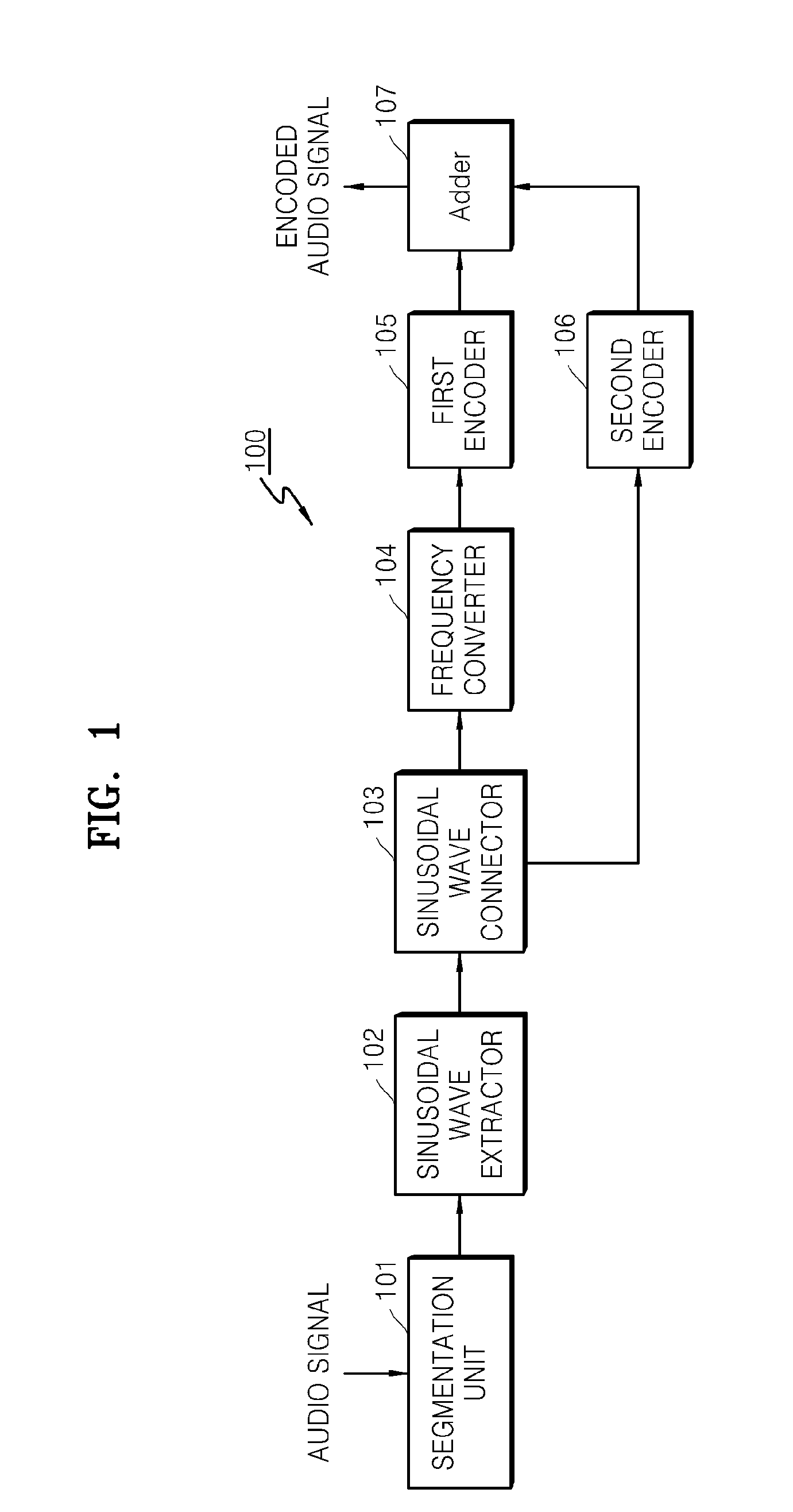
[0037]FIG. 1 is a block diagram of an audio encoding apparatus 100 according to an exemplary embodiment of the present invention. Referring to FIG. 1, the audio encoding apparatus 100 includes a segmentation unit 101, a sinusoidal wave extractor 102, a sinusoidal wave connector 103, a frequency converter 104, a first encoder 105, a second encoder 106, and a adder 107.

[0038]The segmentation unit 101 segments an input audio signal by a specific length L in a time domain, wherein the specific length L is an integer. Thus, if an audio signal output from the segmentation unit 101 is S(n), n is a temporal index and can be defined as n=1˜L. When the input audio signal is segmented by the specific length L, the segmented audio signals may overlap with a previous segment by an amount of L / 2 or by a specific length.

[0039]The sinusoid...


PUM


Abstract

Provided is an audio encoding and decoding apparatus and method for improving a compression ratio while maintaining sound quality when sinusoidal waves of an audio signal are connected and encoded. The audio encoding method includes connecting sinusoidal waves of an input audio signal, converting a frequency of each of the connected sinusoidal waves to a psychoacoustic frequency, performing a first encoding operation for encoding the psychoacoustic frequency, performing a second encoding operation for encoding an amplitude of each of the connected sinusoidal waves, and outputting an encoded audio signal comprising the encoding result of the first encoding operation and the encoding result of the second encoding operation.

Description

CROSS-REFERENCE TO RELATED PATENT APPLICATION[0001]This application claims priority from Korean Patent Application No. 10-2007-0014558, filed on Feb. 12, 2007, in the Korean Intellectual Property Office, the disclosure of which is incorporated herein in its entirety by reference.BACKGROUND OF THE INVENTION[0002]1. Field of the Invention[0003]Apparatuses and methods consistent with the present invention relate to audio encoding and decoding, and more particularly, to connecting and encoding sinusoidal waves of an audio signal.[0004]2. Description of the Related Art[0005]Parametric coding is a method of segmenting an input audio signal by a specific length in a time domain and extracting sinusoidal waves with respect to the segmented audio signals. As a result of the extraction of the sinusoidal waves, if sinusoidal waves having similar frequencies are continued over several segments in the time domain, the sinusoidal waves having similar frequencies are connected and encoded using th...

Claims


Application Information

Patent Timeline
Patent Type & Authority Patents(United States)
IPC IPC(8): G10L11/04G10L19/08G10L19/093G10L25/90
CPCG10L19/093G10L19/02H03M7/30G10L19/04G11B20/10
Inventor LEE, GEON-HYOUNGOH, JAE-ONELEE, CHUL-WOOJEONG, JONG-HOONLEE, NAM-SUK
Owner SAMSUNG ELECTRONICS CO LTD
Why Eureka
Try Eureka