Vacuum cleaner and intake port unit thereof

a vacuum cleaner and intake port technology, applied in the field of vacuum cleaners, can solve the problems of reducing the cleaning power of steam, and affecting the cleaning effect of vacuum cleaners

Active Publication Date: 2011-11-15
LG ELECTRONICS INC
View PDF26 Cites 10 Cited by
  • Summary
  • Abstract
  • Description
  • Claims
  • Application Information

AI Technical Summary

Benefits of technology

[0015]An object of the present invention is to provide a vacuum cleaner and intake port unit thereof, by which a steam cleaning can be conducted together with a vacuum cleaning and by which a flow path of steam can be reduced.
[0024]More preferably, the boiler further includes a shield positioned between the upper end of the steam discharge pipe and the upper wall of the boiler case to prevent condensed water from entering the steam discharge pipe. More preferably, the shield has a conical shape with a downwardly increasing circumference to prevent condensed water on the upper wall of the boiler case, and condensed water on a bottom of the shield, from entering the steam discharge pipe.
[0033]More preferably, the boiler further includes a shield positioned between the upper end of the steam discharge pipe and the upper wall of the boiler case to prevent condensed water from entering the steam discharge pipe.

Problems solved by technology

However, vacuum cleaners which perform cleaning by only sucking air have difficulty in cleaning up particles stuck on a floor, or removing stains from a floor.
First, the related art steam cleaner is not provided with a vacuum cleaning function, and thus does not permit normal vacuum cleaning. Accordingly, a separate vacuum cleaner is also required.
Second, in order to smoothly remove filth or stains from a floor, a pressure of steam blown from the head part should be maintained at a prescribed level. However, since the burner unit 20 generating the steam is provided within the unit 10, the steam generated from the burner unit 20 must be carried to the head part 50 via the connecting hose 40, which results in a lengthy flow path for the steam. The pressure and temperature of the steam are lowered during the lengthy flow, so that cleaning power of the steam is reduced. In order to compensate for this problem, the blowing pressure and temperature of the steam generated from the burner unit must be set higher. This raises product and operation costs for the cleaner.

Method used


Image

  • Vacuum cleaner and intake port unit thereof
  • Vacuum cleaner and intake port unit thereof
  • Vacuum cleaner and intake port unit thereof

Examples


Embodiment Construction

[0043]Reference will now be made in detail to the preferred embodiments of the present invention, examples of which are illustrated in the accompanying drawings. Wherever possible, the same reference numbers will be used throughout the drawings to refer to the same or like parts.

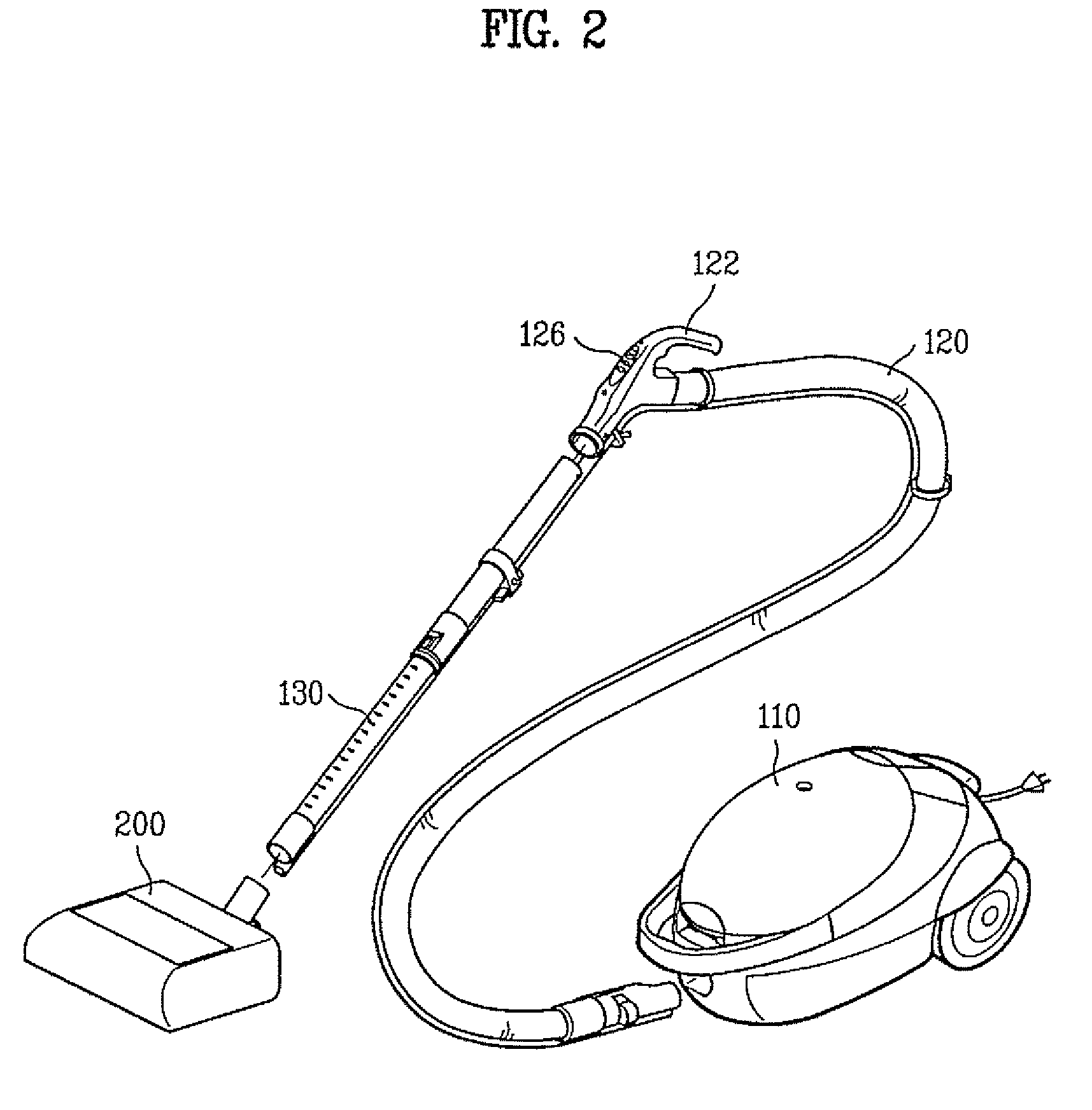
[0044]A vacuum cleaner and intake port unit thereof according to one embodiment of the present invention are explained with reference to FIGS. 2 to 7.

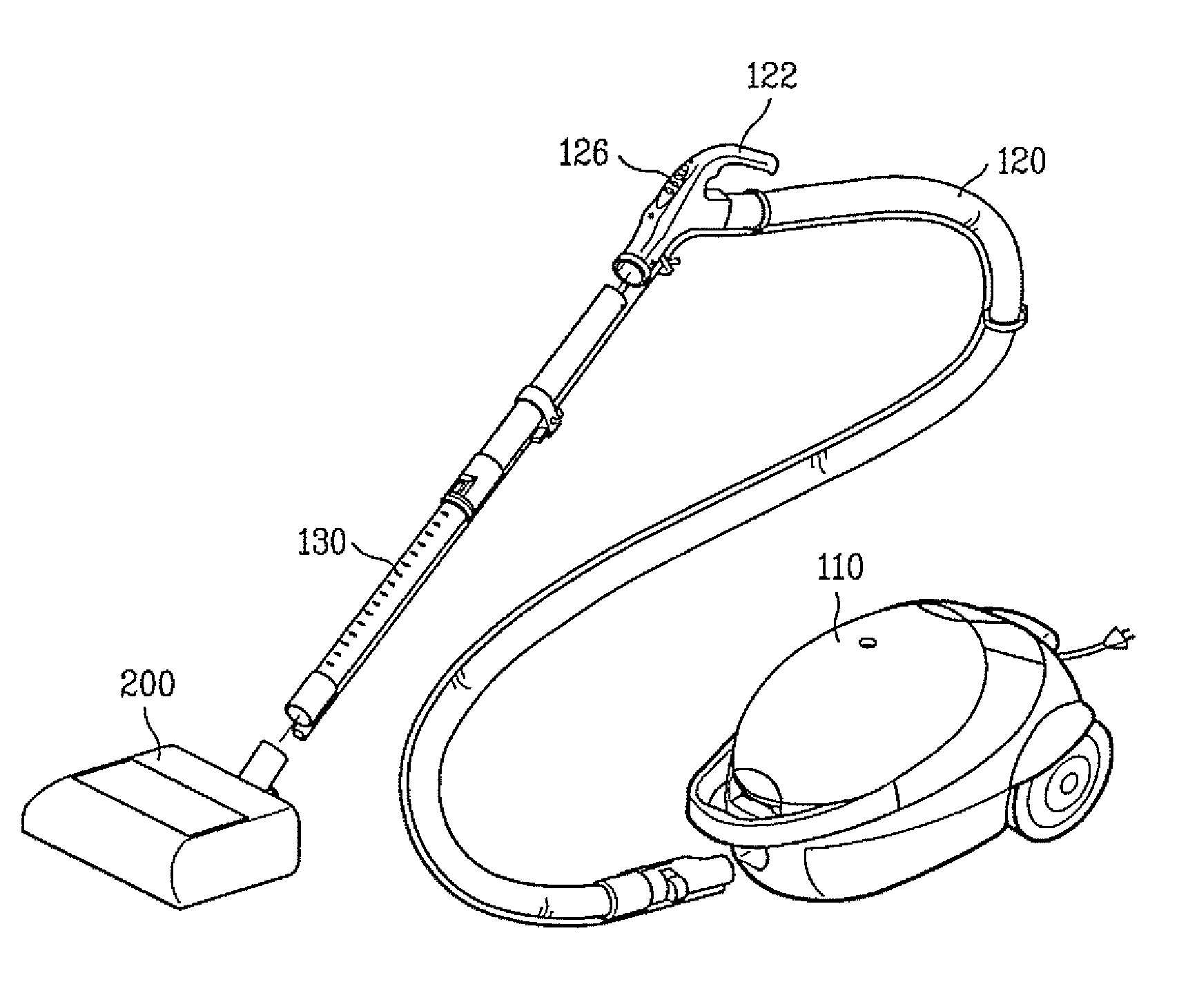
[0045]FIG. 2 is a perspective view of a vacuum cleaner according to one embodiment of the present invention. Referring to FIG. 2, a vacuum cleaner according to one embodiment of the present invention includes a vacuum or cleaner unit 110 which generates a strong air suction force created by a vacuum source. This may be provided in any suitable manner, such as by operation of a motor provided in the vacuum unit 110. An extension pipe 120 is connected to extend from the vacuum unit 110 to guide and carry air and dust to an inside of the vacuum unit 110, and an in...


PUM


Abstract

A vacuum cleaner and an intake port unit thereof are disclosed, by which a steam cleaning can be conducted together with a vacuum cleaning. The intake port unit includes a housing. A vacuum intake passage is provided within the housing for passage of air sucked in from the exterior of the housing, and a steam generator is provided within the housing to generate steam. A steam discharge passage is provided within the housing for passage of steam discharged to the exterior of the housing. The steam discharge passage is partitioned from the vacuum intake passage.

Description

[0001]This application claims the benefit of the Korean Patent Application No. 10-2005-0122520, filed on Dec. 13, 2005, which is hereby incorporated by reference in its entirety.BACKGROUND OF THE INVENTION[0002]1. Field of the Invention[0003]The present invention relates to a vacuum cleaner, and more particularly, to a vacuum cleaner and intake port unit thereof. Although the present invention is suitable for a wide range of applications, it is particularly suitable for performing both vacuum cleaning and steam cleaning.[0004]2. Discussion of the Related Art[0005]Generally, a vacuum cleaner is a device that performs cleaning by sucking in air with dirt or dust from a floor or surface, filtering out the dirt or dust, and discharging the air. Vacuum cleaners are popularly used due to their convenience of use.[0006]However, vacuum cleaners which perform cleaning by only sucking air have difficulty in cleaning up particles stuck on a floor, or removing stains from a floor. Recently, eff...

Claims


Application Information

Patent Timeline
Patent Type & Authority Patents(United States)
IPC IPC(8): A47L11/30
CPCA47L5/36A47L9/02A47L9/0686A47L11/34A47L11/4086A47L11/4094F22B1/284A47L11/00A47L11/20
Inventor KIM, HYOUNG JUNCHOI, JAY HOPARK, SUNG ILCHUNG, CHOON MYUN
Owner LG ELECTRONICS INC
Why Eureka
Try Eureka