
Concealed suspension ceiling with downward removable panels

a technology of suspended ceilings and panels, applied in the direction of walls, constructions, building components, etc., can solve the problems of limiting the places where ordinary systems can be used as well as aesthetics, and requiring a minimum of overhead clearan

Active Publication Date: 2011-11-15
USG INTERIORS INC
View PDF26 Cites 23 Cited by
  • Summary
  • Abstract
  • Description
  • Claims
  • Application Information

AI Technical Summary

Benefits of technology

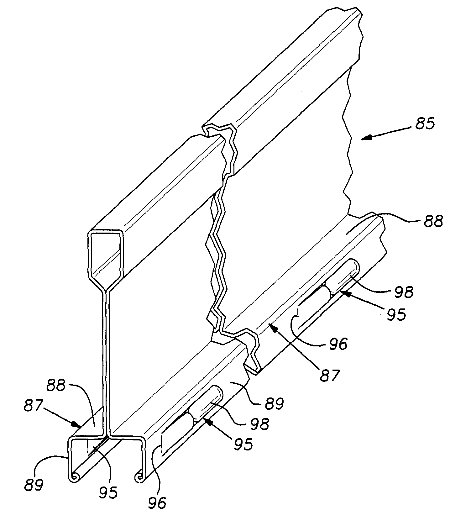
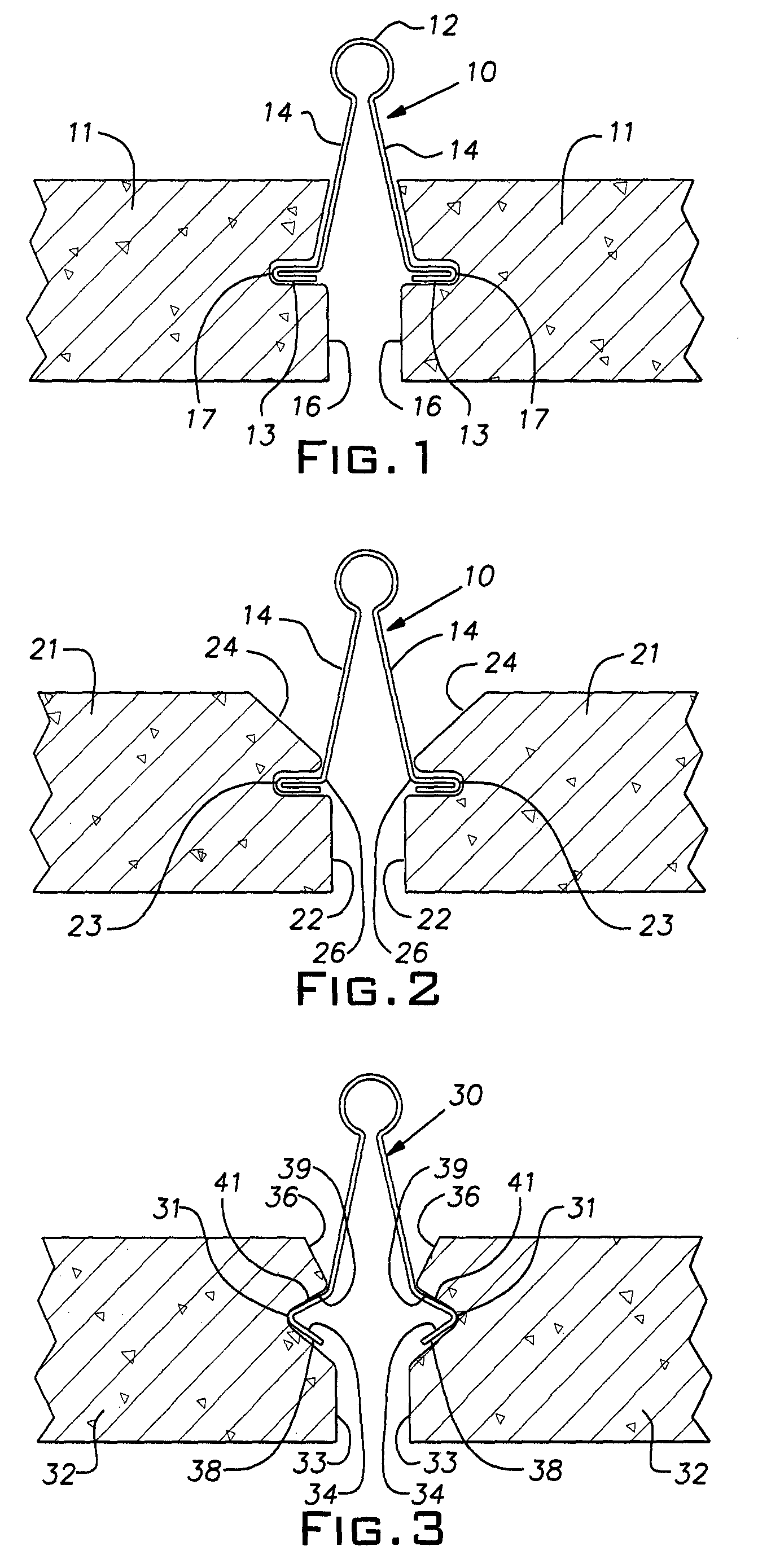
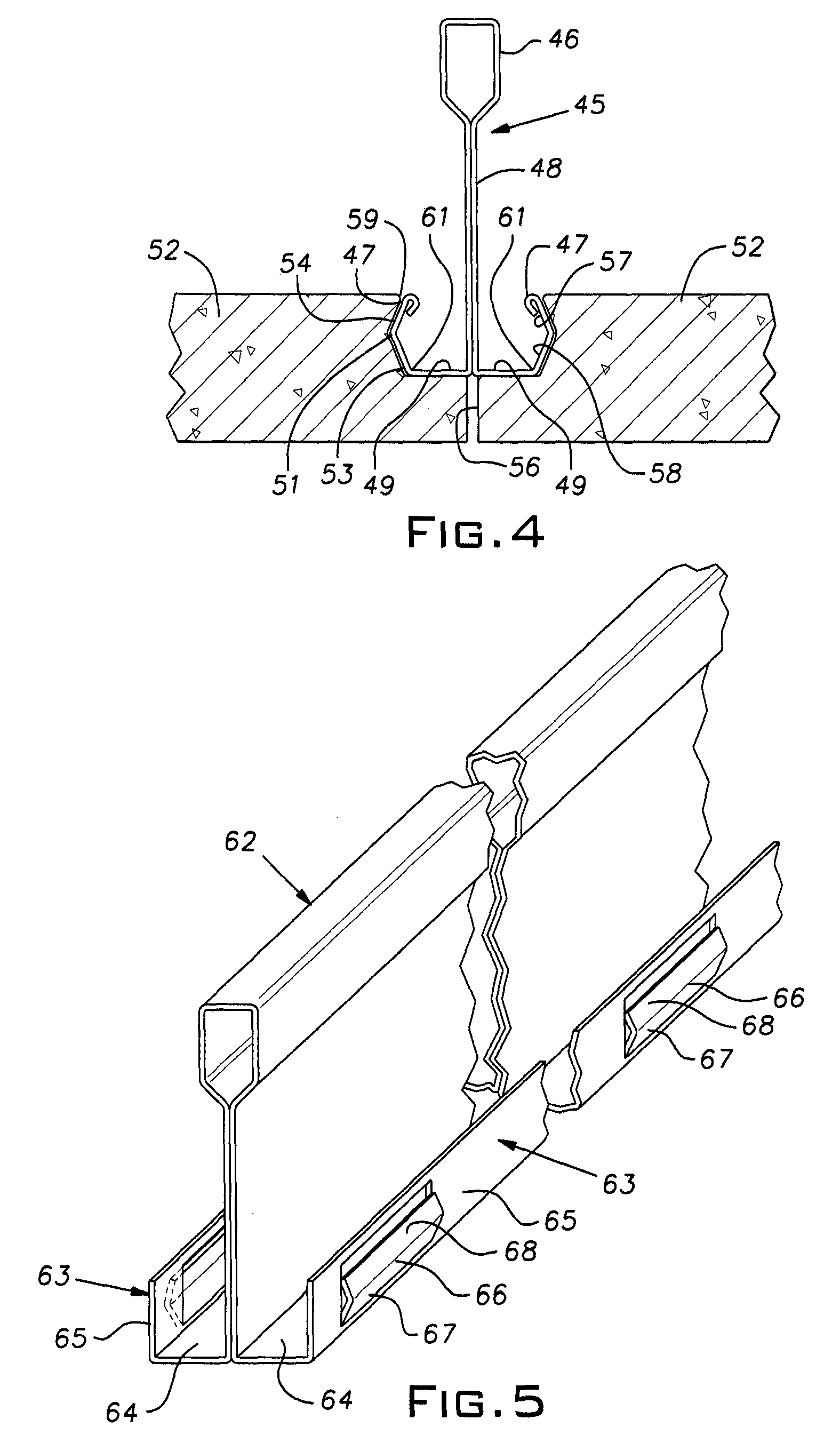
The invention is about creating components for suspended ceilings that allow panels to be easily installed and removed. The panels are supported by a grid made up of interlocking members. The panels have special elements on their edges that fit into spaces on the grid members, allowing for easy movement. The panels can be installed or removed by moving them up or down. The design works well for both movements.

Problems solved by technology

While this installation technique allows the grid elements and panels to take simple forms, it requires some minimum overhead clearance and usually leaves the lower face of the grid elements fully exposed.
These characteristics can limit the places where these ordinary systems can be used as well as the aesthetics of such installations.

Method used


Image

  • Concealed suspension ceiling with downward removable panels
  • Concealed suspension ceiling with downward removable panels
  • Concealed suspension ceiling with downward removable panels

Examples


Embodiment Construction

[0019]The grid members described herein will be typically formed of rolled sheet metal strips of steel or aluminum as is customary in the industry. The grid members, commonly, have the general cross-sectional shape of an inverted T with the bottom having a panel supporting flange and the top having a hollow reinforcing bulb. The grid members or tees, in a customary manner, are arranged in a rectangular grid, ordinarily using long main runners and short cross runners. The grid module, for example, can be 2′×2′ or 2′×4′, or metric equivalent, as well as other desired sizes. It will be well understood that the various tees disclosed herein can be used in only one direction, with conventional tee shapes in the other direction, so that a rectangular panel is supported on two opposite edges or, alternatively, can be used in both directions so that the panel is supported on all four edges. The ceiling panels described herein are typically rectangular (which term includes square) composite ...


PUM


Abstract

A suspended ceiling system comprising metal grid members and rectangular composite acoustical panels, the panels having edges at their peripheries, the grid members having a cross section generally like an inverted T such that they provide oppositely extending flanges adapted to support the panels at their edges, a resilient element at a juncture between a support on the grid member flanges and at least one edge of each panel, the resilient element being arranged to temporarily deflect to permit a panel to be raised from below the grid member into an installed position and to extend itself to hold such panel in position on the grid.

Description

[0001]The invention relates to suspended ceiling constructions and, in particular, to systems in which ceiling panels are downwardly removable from a suspended grid.BACKGROUND OF THE INVENTION[0002]Suspended ceilings ordinarily comprise a rectangular metal grid and panels or tiles that are set in the grid spaces from the plenum above the plane of the grid. While this installation technique allows the grid elements and panels to take simple forms, it requires some minimum overhead clearance and usually leaves the lower face of the grid elements fully exposed. These characteristics can limit the places where these ordinary systems can be used as well as the aesthetics of such installations.SUMMARY OF THE INVENTION[0003]The invention provides grid and panel components for suspended ceilings that allow the panel to be installed and removed from the grid by movement through the space below the ceiling. The invention relies on laterally resilient elements disposed where the edges of the p...

Claims


Application Information

Patent Timeline
Patent Type & Authority Patents(United States)
IPC IPC(8): E04B9/00
CPCE04B9/06E04B9/28E04B9/26E04B9/068E04B9/22
Inventor LALONDE, PAUL D.
Owner USG INTERIORS INC
Learn More