
Cable assembly having improved insulative holding device and method for making the same

a technology of insulating holding device and cable assembly, which is applied in the direction of electrical equipment, line/current collector details, coupling device connections, etc., can solve the problem of low cost of manufacturing the cable assembly, and achieve the effect of low cost, reliable fastening of the cable, and simple structur

Inactive Publication Date: 2011-11-15
HON HAI PRECISION IND CO LTD
View PDF12 Cites 5 Cited by
  • Summary
  • Abstract
  • Description
  • Claims
  • Application Information

AI Technical Summary

Benefits of technology

[0009]An object of the present invention is to provide a cable assembly having low costed insulative holding device capable of fastening the cable reliably and having simple structure.
[0011]The insulative holding device of the cable assembly encloses the insulative sheath and the conductors simultaneously. The structure of insulative holding device is simple. The cost of manufacturing the cable assembly is low.

Problems solved by technology

The cost of manufacturing the cable assembly is low.

Method used


Image

  • Cable assembly having improved insulative holding device and method for making the same
  • Cable assembly having improved insulative holding device and method for making the same
  • Cable assembly having improved insulative holding device and method for making the same

Examples


Embodiment Construction

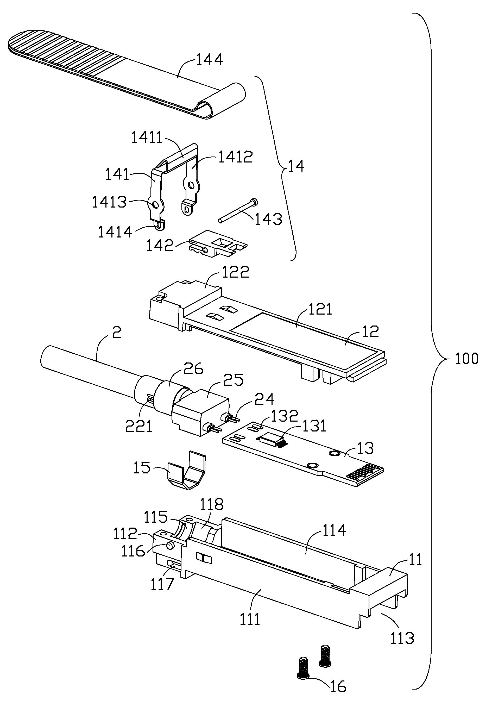
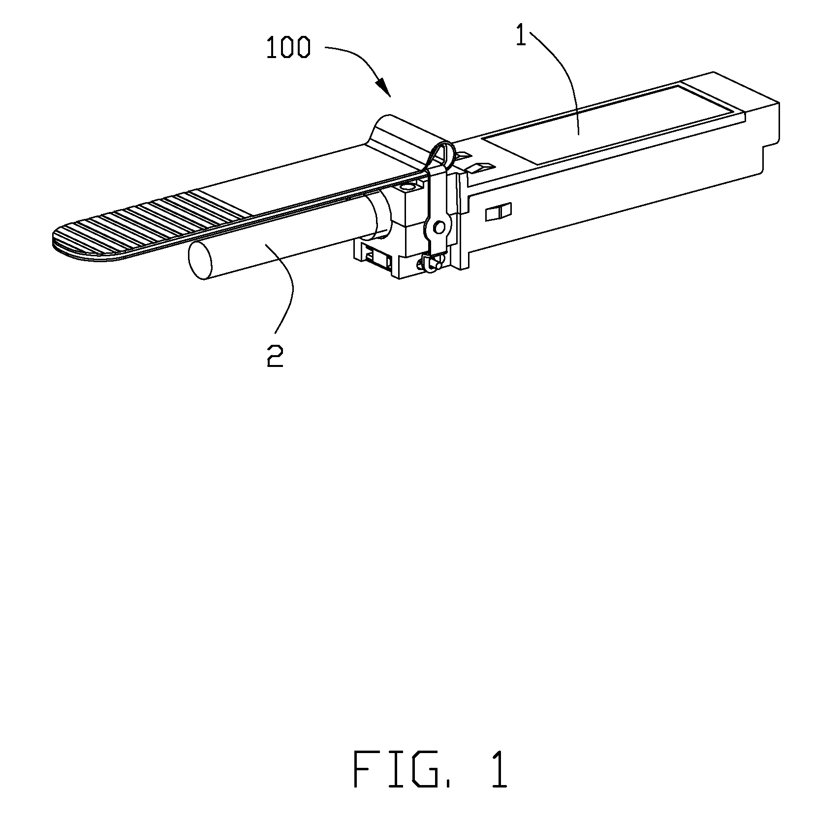
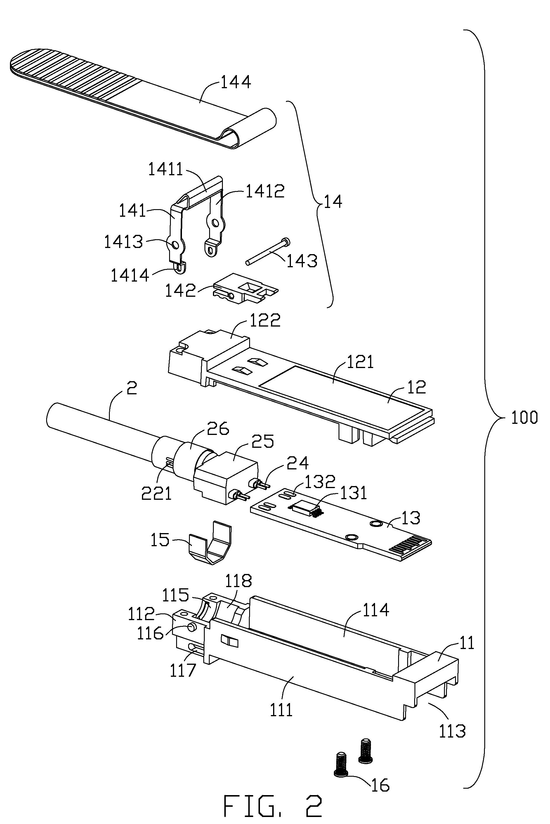
[0017]Reference will now be made to the drawing figures to describe the present invention in detail. Referring to FIGS. 1-2, a cable assembly 100 according to the present invention is a SFP module. The cable assembly 100 comprises a module 1 and a cable 2 connecting to the module 1.

[0018]Referring to FIG. 2, the module 1 comprises a bottom shell 11, a top shell 12 coupling with the bottom shell 11, an interior PCB 13 received in the bottom shell 11, and a releasing device 14. The bottom shell 11 comprises a base portion 111 and a cable-receiving portion 112. The base portion 111 defines a cutout 113 for engaging with a mating connector (not shown) and a first cavity 114 for insertion of the mating connector. The cable-receiving portion 112 defines a half-cylindrical second cavity 115, a pair of cylindrical posts 116 and a slot 117. Part of the second cavity 115 is formed with a recess 118. The top shell 12 comprises a flat portion 121 covering the first cavity 114 and a connection p...


PUM

PropertyMeasurementUnit
circumferenceaaaaaaaaaa
conductiveaaaaaaaaaa
structureaaaaaaaaaa

Abstract

A cable assembly (100) includes an interior printed circuit board (13) with a number of conductive pads (132), a cable (2) and an insulative holding device (25). The cable (2) includes a number of conductors (21), a conductive sheath (22) shrouding the conductors (21) and an insulative sheath (23) shrouding the conductive sheath (22). Each conductor (22) has a soldering tail (24) extending to the outside of the insulative sheath (23) and soldering to the conductive pad (132). The insulative holding device (25) encloses the insulative sheath (22) and the conductors (21).

Description

BACKGROUND OF THE INVENTION[0001]1. Field of the Invention[0002]The present invention relates to a cable assembly having an improved cable holding device adapted for fastening the cable and a method for producing the same.[0003]2. Description of Related Art[0004]U.S. Pat. No. 7,090,527 issued on Aug. 15, 2006 discloses a SFP (Small Form Factor Pluggable) module. The SFP module comprises a cable having a number of conductive cores, a top shell, a bottom shell and an interior PCB (printed circuit board). A metal ring is attached to one end of the cable. The conductive cores of the cable extend outside of the metal ring for soldering on the interior PCB. One side of the bottom shell defines a cavity for receiving the interior PCB. Another side of the bottom shell defines a slot receiving the metal ring. The top shell covers on the bottom shell to hold the interior PCB and cable stably.[0005]The conductive cores of the cable are not fixed in any predetermined position and thereby are ha...

Claims


Application Information

Patent Timeline
Patent Type & Authority Patents(United States)
IPC IPC(8): H01R9/03
CPCH01R13/6658H01R9/034Y10T29/49117H01R13/65914
Inventor ZHU, QING-MANZHANG, XUE-LIANGWANG, CHIEN-CHIUNG
Owner HON HAI PRECISION IND CO LTD
Learn More