Semi-powered lower extremity exoskeleton

a lower extremity and exoskeleton technology, applied in the field of lower extremity exoskeletons, can solve the problems of people of ordinary ability being frustrated in attempting to carry excessively heavy or bulky objects, and people cannot even carry their own weight, so as to achieve the effect of quickly tiredness or injury

Active Publication Date: 2011-11-15
RGT UNIV OF CALIFORNIA
View PDF45 Cites 123 Cited by
  • Summary
  • Abstract
  • Description
  • Claims
  • Application Information

AI Technical Summary

Benefits of technology

[0007]The opportunities described above are addressed in several embodiments of a lower extremity exoskeleton, wearable by a person. The lower extremity exoskeleton comprises two leg supports connectable to person's lower limbs and configured to rest on the ground during their stance phase. Each leg support comprises a thigh link and a shank link; a knee joint configured to allow flexion and extension between the shank link and the thigh link. The lower extremity exoskeleton further comprises an exoskeleton trunk connectable to the person's upper body. The exoskeleton trunk is connectable to the thigh links of the leg supports allowing for the flexion and extension between the leg supports and the exoskeleton trunk. Two torque generators are coupled to each of the knee joints. A power unit, capable of providing power, is coupled to the torque generators. In operation when a leg support is in a stance phase and climbing a slope or stairs, the power unit injects power into the respective torque generator thereby extending the respective knee angle. When a leg support is in stance phase and not climbing a slope or stairs, the power unit does not inject any power to the respective torque generator, but without dissipating any stored power in said power unit, it forces the torque generator to resist flexion of the respective knee joint. When a leg support is in a swing phase, the power unit does not inject any power to the respective torque generator, but without dissipating any stored power in said power unit, it forces the torque generator to minimize its resistance to knee flexion and extension.

Problems solved by technology

In a wide variety of situations, people of ordinary ability are often frustrated in attempting to carry excessively heavy or bulky objects while walking on slopes and stairs.
Some people cannot even carry their own weights without becoming tired quickly or injured.

Method used


Image

  • Semi-powered lower extremity exoskeleton
  • Semi-powered lower extremity exoskeleton
  • Semi-powered lower extremity exoskeleton

Examples


Embodiment Construction

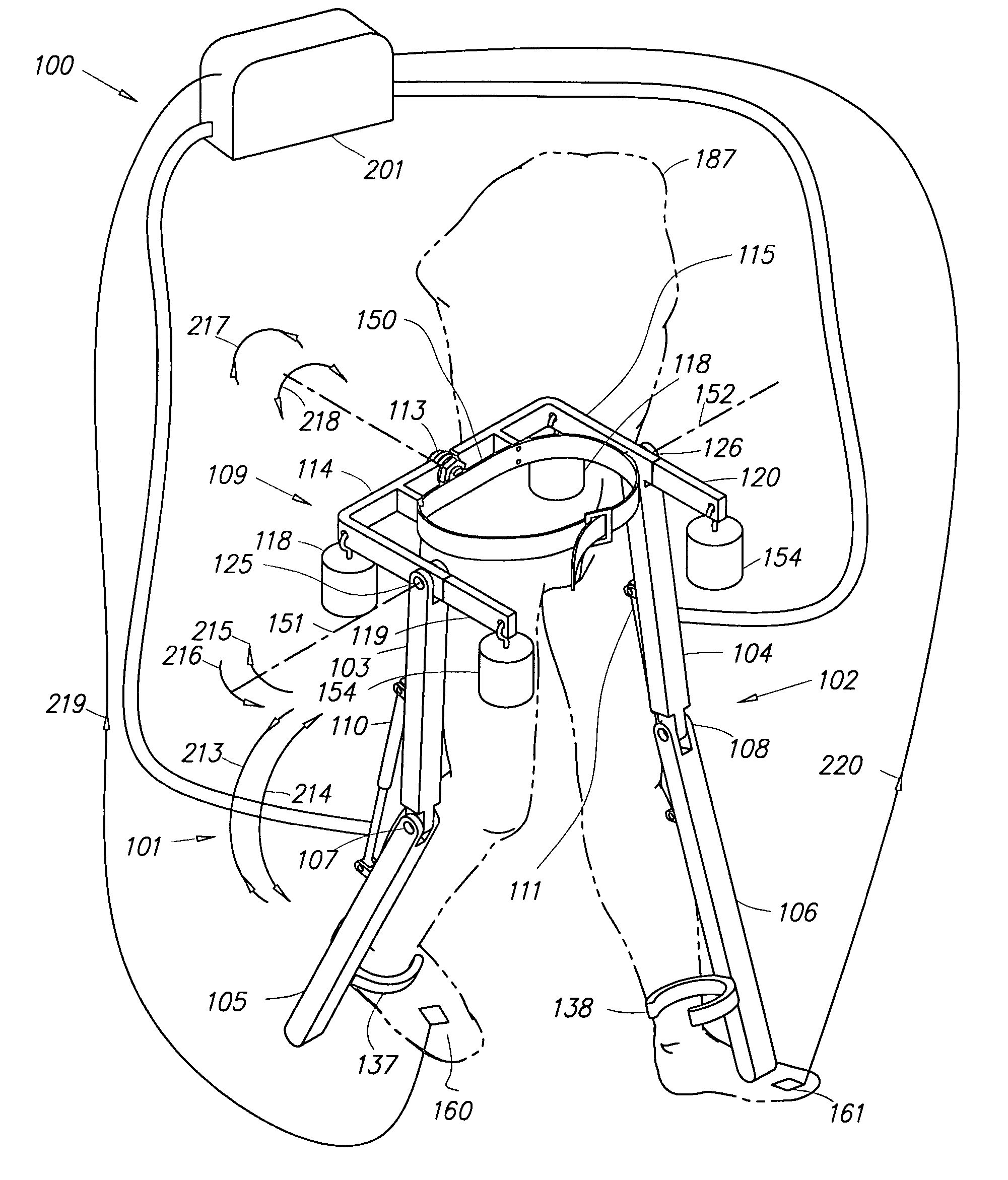
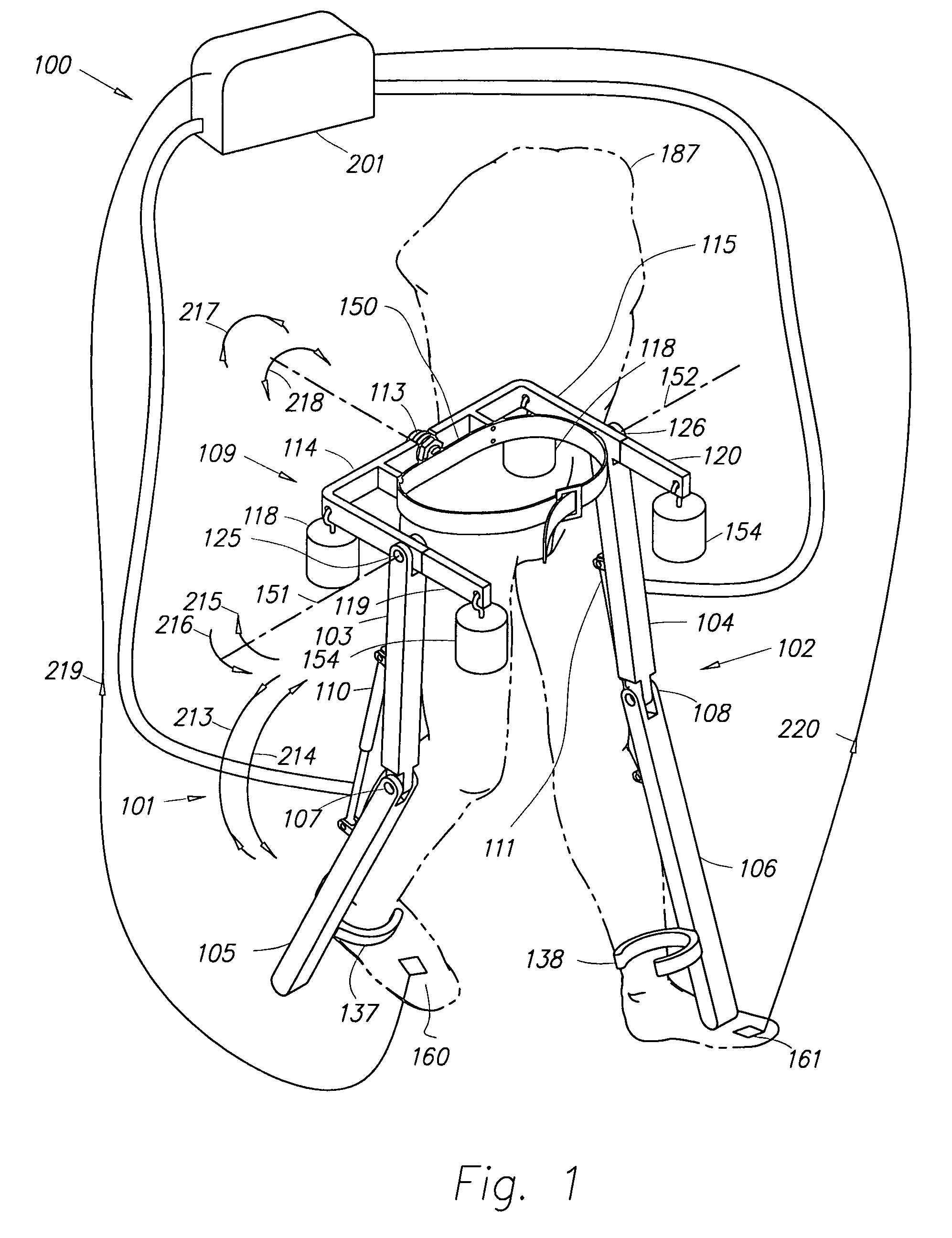
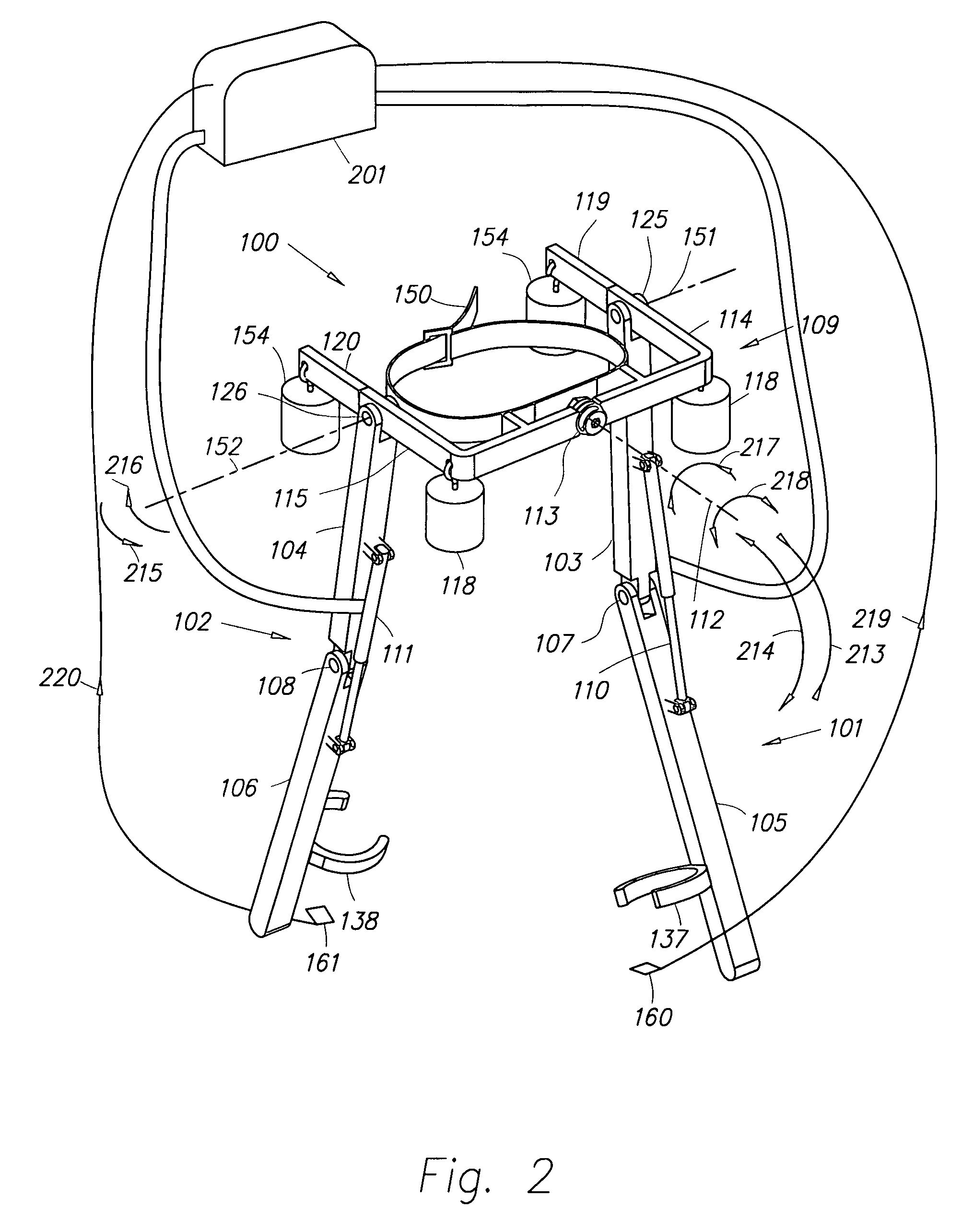
[0045]In accordance with an embodiment of the present invention, FIG. 1 and FIG. 2 are perspective drawings illustrating a lower extremity exoskeleton 100 wearable by a person 187. Lower extremity exoskeleton 100 comprises two leg supports 101 and 102, which are configured to be connectable to the person's lower limbs and configured to rest on the ground during their stance phase. The leg supports comprise thigh links 103 and 104 and shank links 105 and 106. Two knee joints 107 and 108 are configured to allow flexion and extension between the shank and thigh of the leg supports (shown by arrows 213 and 214 respectively). Lower extremity exoskeleton 100 further comprises an exoskeleton trunk 109. Exoskeleton trunk 109, among other components, comprises a human interface device 150. Exoskeleton trunk 109 is configurable to be coupled to the person's upper body through human interface device 150. The person's upper body means any location above the thighs. Exoskeleton trunk 109 is rota...


PUM


Abstract

The lower extremity exoskeleton comprises two leg supports connectable to person's lower limbs and configured to rest on the ground during their stance phase. Each leg support comprises a thigh link and a shank link; a knee joint configured to allow flexion and extension between the shank link and the thigh link. The lower extremity exoskeleton further comprises an exoskeleton trunk connectable to the person'supper body. The exoskeleton trunk is connectable to the thigh links of the leg supports allowing for the flexion and extension between the leg supports and the exoskeleton trunk. Two torque generators are coupled to each of the knee joints. A power unit, capable of providing power, is coupled to the torque generators. In operation when a leg support is in a stance phase and climbing a slope or stairs, the power unit injects power into the respective torque generator thereby extending the respective knee angle. When a leg support is in stance phase and not climbing a slope or stairs, the power unit does not inject any power to the respective torque generator, but without dissipating any stored power in said power unit, it forces the torque generator to resist flexion of the respective knee joint. When a leg support is in a swing phase, the power unit does not inject any power to the respective torque generator, but without dissipating any stored power in said power unit, it forces the torque generator to minimize its resistance to knee flexion and extension.

Description

CROSS-REFERENCE TO RELATED APPLICATIONS[0001]This application claims the benefit of U.S. Provisional Application No. 60 / 671,348, titled SEMI-POWERED LOWER EXTREMITY EXOSKELETON, filed Apr. 13, 2005, the entire content of which is incorporated herein by reference.STATEMENT REGARDING FEDERALLY SPONSORED RESEARCH OR DEVELOPMENT[0002]This invention was made with government support under Contract No. DAAD19-01-1-0509 awarded by Defense Advanced Research Projects Agency (DARPA). The government has certain rights in the invention.BACKGROUND[0003]1. Field[0004]The present invention relates generally to the field of lower extremity exoskeletons and more specifically to the field of semi-powered lower extremity exoskeletons.[0005]2. Related Art[0006]In a wide variety of situations, people of ordinary ability are often frustrated in attempting to carry excessively heavy or bulky objects while walking on slopes and stairs. Some people cannot even carry their own weights without becoming tired q...

Claims


Application Information

Patent Timeline
Patent Type & Authority Patents(United States)
IPC IPC(8): A61H3/00
CPCA61H3/00A61H3/008B25J9/0006A61H1/024A61B5/1038A61H2201/5061A61F5/0102A61H1/0237A61H2201/1614A61H2201/1238A61H2201/1616A61H2201/1621A61H2201/1623A61H2201/1628A61H2201/163A61H2201/1635A61H2201/164A61H2201/1642A61H2201/165A61H2201/1676A61B5/4528
Inventor ANGOLD, RUSSDONHARDING, NATHAN H.KAZEROONI, HOMAYOON
Owner RGT UNIV OF CALIFORNIA
Why Eureka
Try Eureka