
Battery busing scheme

a battery and busing technology, applied in the field of multi-cell batteries, to achieve the effect of ensuring safe passage of large amounts of current and more efficient battery power

Active Publication Date: 2011-11-15
SECURAPLANE TECH
View PDF14 Cites 4 Cited by
  • Summary
  • Abstract
  • Description
  • Claims
  • Application Information

AI Technical Summary

Benefits of technology

[0003]In today's high demand for more efficient battery power and the development of thin plate batteries, methods of incorporating these cells into industry applications has led to creating new busing concepts and circuit protection that was not required for past battery technologies. The battery packs must meet the high power demands and be capable of passing large amounts of current safely from the thin plate battery assemblies. Moreover, the thin plate batteries allow one to utilize minimal space for the applications enclosure with all the components required for the battery technology.
[0005]With the introduction of the thin plate cells into high-power applications, the high current output levels require busing methods that can handle those current loads with minimal impedance and without any resulting damage to the cells. The anode and cathode plates from which the power is extracted from the battery are of very sensitive parts of the packaging and must be able to withstand vibration. The concepts described herein will allow one to safely bus the batteries together and design a complete, capacity-rated output battery for the required application.
[0006]The busing concept described herein utilizes components that enable one to reduce the assembled height of the packaging of the battery pack as compared to prior art. The concept reduces the need for large gauge inter-connect cabling by incorporating bus clamps for the main power inter-connects. Internal monitoring circuitry can also be incorporated into a printed circuit board which is part of the bus assembly. Utilizing all of the components of the concepts described herein will allow a minimal envelope for the battery pack into its enclosure.
[0011]Depending on the configuration, current capacity, and maximum output requirements of the battery, in prior art designs simple wiring of the current from one cell to another necessitated not only numerous interconnections but also space to accommodate that wiring.

Problems solved by technology

Depending on the configuration, current capacity, and maximum output requirements of the battery, in prior art designs simple wiring of the current from one cell to another necessitated not only numerous interconnections but also space to accommodate that wiring.

Method used


Image

  • Battery busing scheme
  • Battery busing scheme
  • Battery busing scheme

Examples


Embodiment Construction

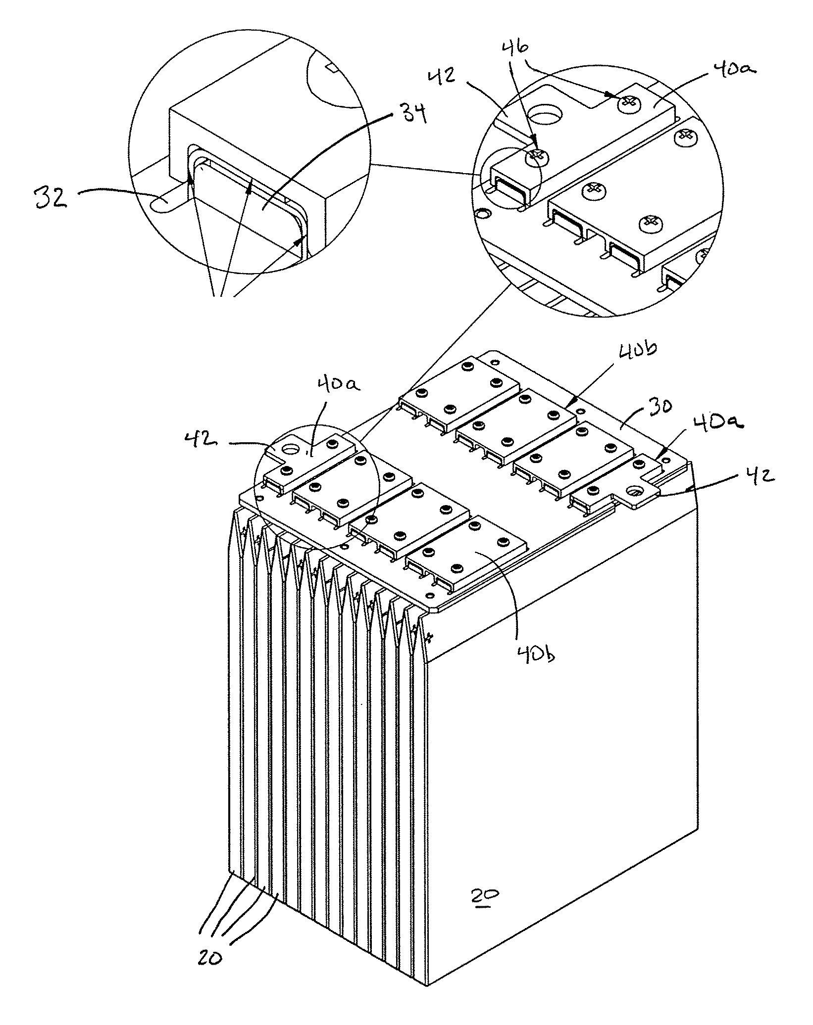
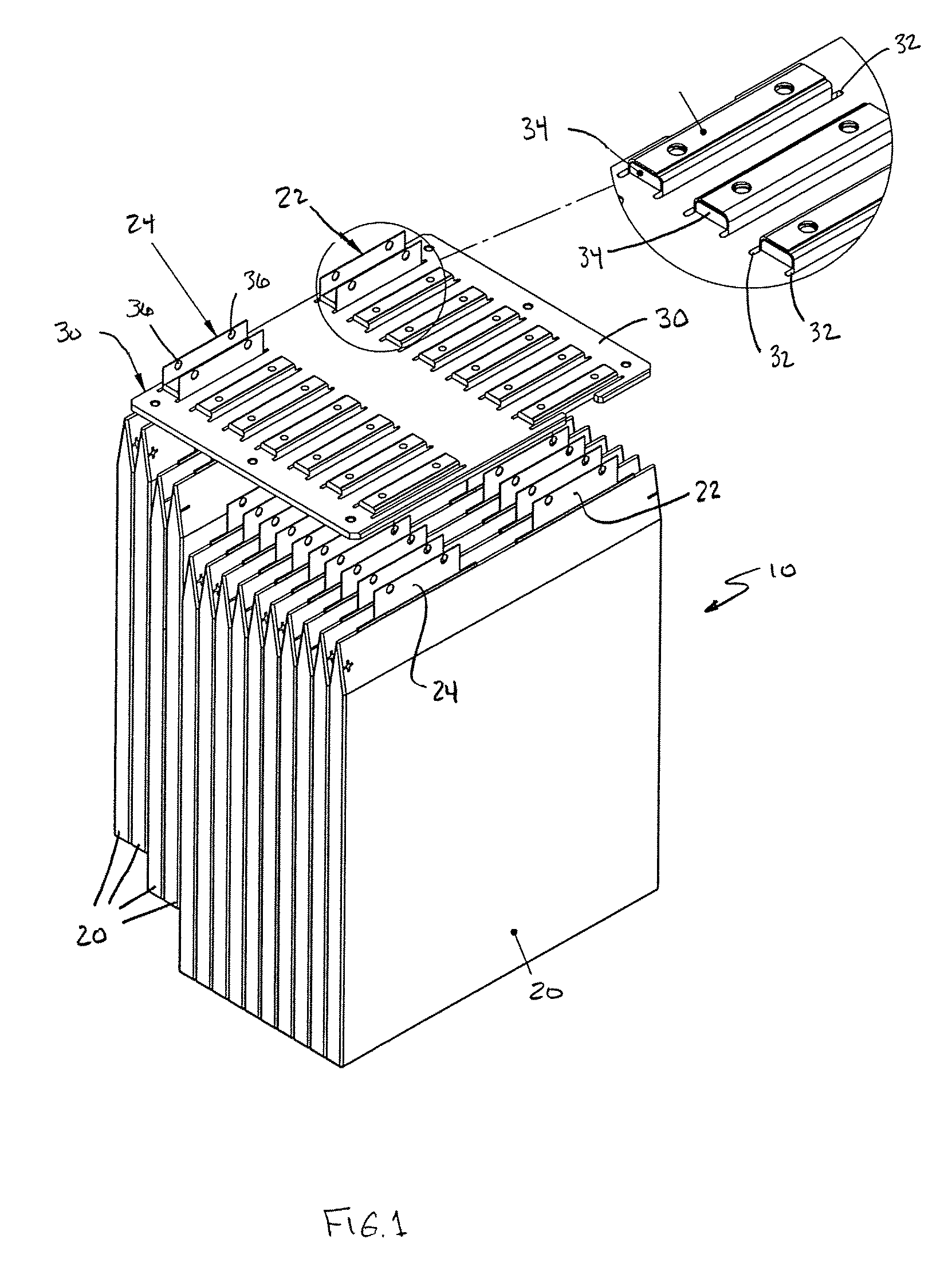
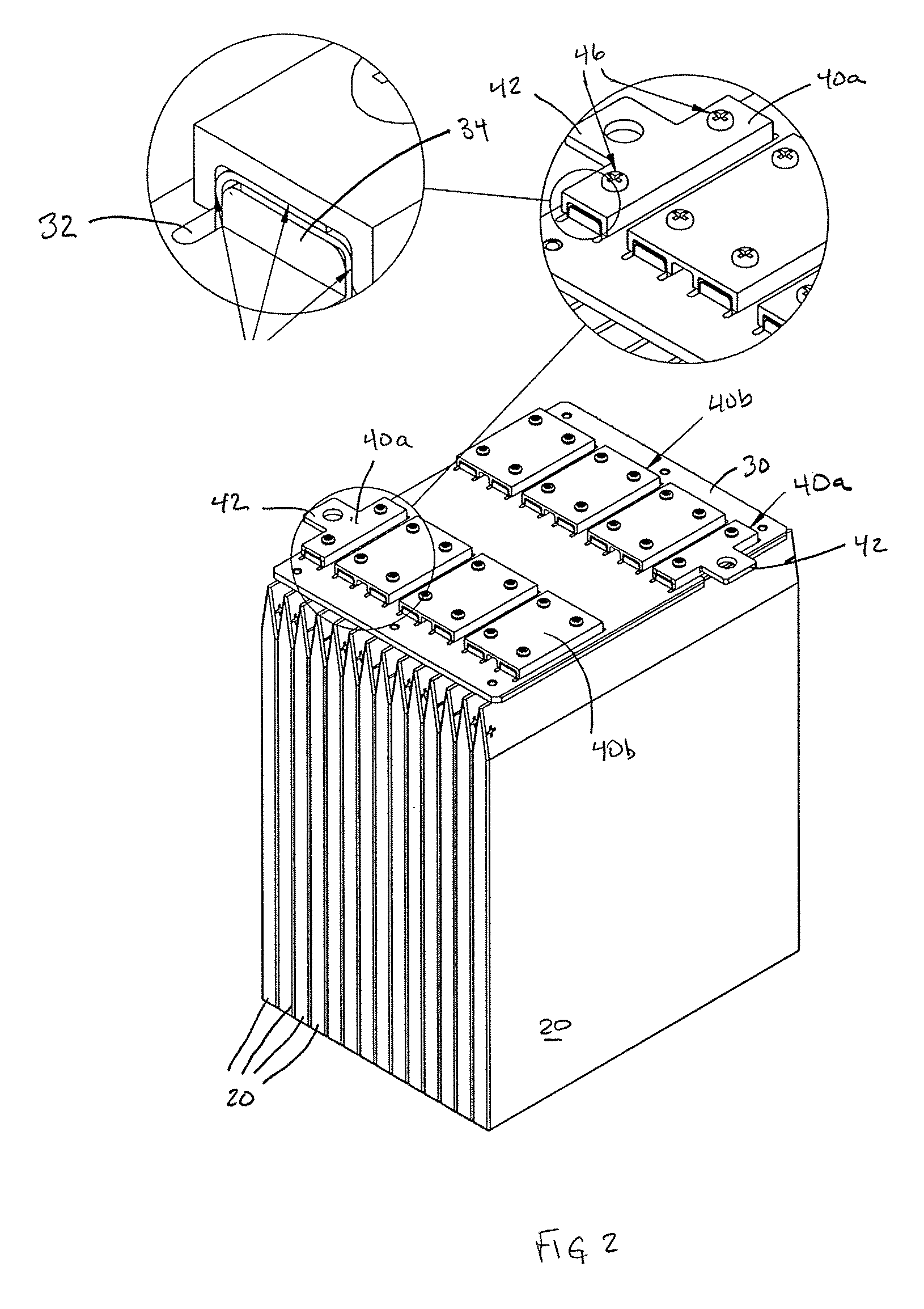
[0017]Referring to FIG. 1, a battery 10 of the described embodiment is made up of a set of thin plate cells 20 arranged next to each other. Each thin plate cell 20 is rectangularly shaped, has a thin profile and includes two terminals plates, a cathode (or negative) terminal plate 22 and an anode (or positive) terminal plate 24, both extending up from the top of the cell. The terminal plates are thin metal tabs made of copper and electroplated plated with tin to prevent corrosion. Cells 20 are all arranged so that all of their terminal plates extend in the same direction, which in FIG. 1 is upward. In this example, there are 14 thin film cells arranged within the battery so that their polarity alternates in pairs. In other words, the first two cells have their anodes on the left, the next two cells have their cathodes on the left, and that pattern repeats for the rest of the cells in the battery. As will become apparent shortly, when the electrical interconnections are described, th...


PUM

PropertyMeasurementUnit
electrically non-conductiveaaaaaaaaaa
electrically conductingaaaaaaaaaa
temperatureaaaaaaaaaa

Abstract

A battery including: a plurality of battery cells arranged side-by-side, each battery cell including a terminal tab for delivering power from the cell; a bus plate made of an electrically non-conductive material, the bus plate also having an array of holes formed therein, the array of holes defining a plurality of hole pairs, wherein the terminal tab from each cell of the plurality of cells extends through a corresponding different hole in the array of holes, wherein for each hole pair of the plurality of hole pairs, the terminal tabs extending through that hole pair are folded one over the other to produce overlapping tabs for that hole pair; and a plurality of clamps each of which clamps together the overlapping tabs of a corresponding different hole pair.

Description

[0001]This application claims the benefit of U.S. Provisional Application No. 60 / 792,876, filed Apr. 18, 2006, all of which is incorporated herein by reference.TECHNICAL FIELD[0002]This invention relates generally to multi-cell batteries and interconnecting the cells of multi-cell batteries.BACKGROUND AND SUMMARY OF THE INVENTION[0003]In today's high demand for more efficient battery power and the development of thin plate batteries, methods of incorporating these cells into industry applications has led to creating new busing concepts and circuit protection that was not required for past battery technologies. The battery packs must meet the high power demands and be capable of passing large amounts of current safely from the thin plate battery assemblies. Moreover, the thin plate batteries allow one to utilize minimal space for the applications enclosure with all the components required for the battery technology.[0004]Applications for thin plate technologies need to meet both safe...

Claims


Application Information

Patent Timeline
Patent Type & Authority Patents(United States)
IPC IPC(8): H01M6/42H01M50/503H01M50/528H01M50/507H01M50/529H01M50/509H01M50/517H01M50/522H01M50/524H01M50/55H01M50/553H01M50/562
CPCH01M2/204H01M10/0436H01M6/40H01M2/30Y02E60/10H01M50/507H01M50/522H01M50/562H01M50/517H01M50/509H01M50/55H01M50/553H01M50/503H01M50/524
Inventor BJORK, JAMES B.
Owner SECURAPLANE TECH
Learn More